
Instruction Manual
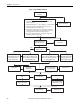
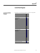
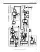
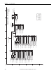
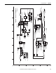
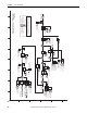
Table Of Contents
- PowerFlex 700S High Performance AC Drive - Phase II Control, Programming Manual
- Summary of Changes
- Table of Contents
- Preface
- Chapter 1 - Drive Start-Up
- Chapter 2 - Programming and Parameters
- Chapter 3 - Troubleshooting
- Appendix A - Human Interface Module Overview
- Appendix B - Application Notes
- Appendix C - Control Block Diagrams
- Appendix D - PowerFlex 700S Permanent Magnet Motor Specifications
- Appendix E - ATEX Approved PowerFlex 700S, Phase II Drives in Group II Category (2) Applications with ATEX Approved Motors
- Appendix F - History of Changes
- Index
- Back Cover
Rockwell Automation Publication 20D-PM001C-EN-P - July 2013 179
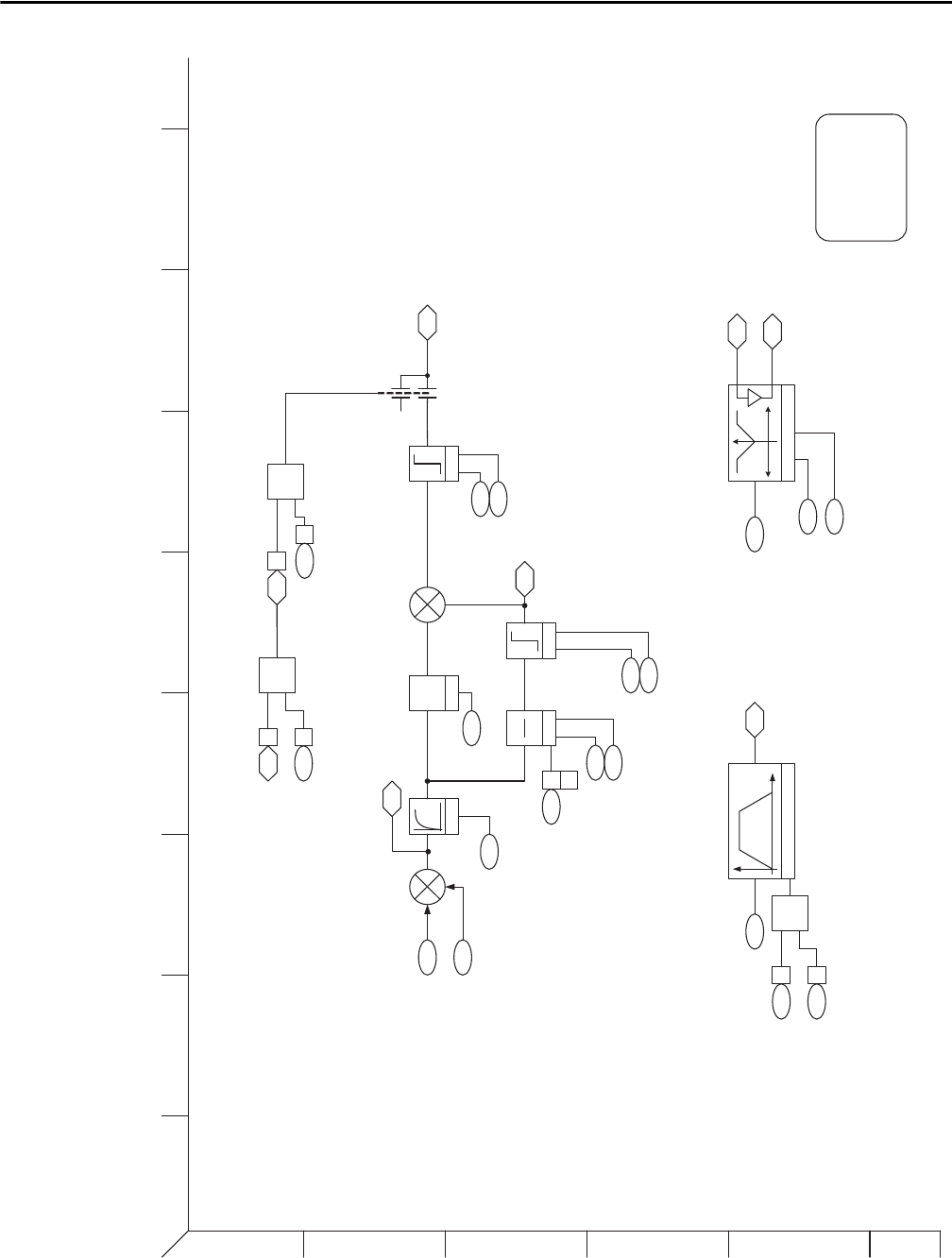
Control Block Diagrams Appendix C
process_control.eps
Process Control
(Task 2)
155 1
151 12
&
157 31
OR
153 23
181
182
184
P Gain
kp
186
185
187
188
189
191
192
180
190
LPass
Filter
Limit
0
1
Logic Status
(Running)
Logic Command
(ProcsTrim En )
Logic Ctrl State
(ProcsTrim En )
Control Options
(PITrim EnOut)
PI Reference
PI Feedback
PI Lpass Filt BW
PI Preload
PI Integ Time
PI Prop Gain
PI Integ HLim
PI Integ LLim
PI Integ Output
PI High Limit
PI Lower Limit
PI Output
0
1
2
3
4
5
6
BA
D
C
FE HG
I
183 PI Error
+
+
OR
202
205
204
206203
207
208
Time Func Generator
Limit Generator
-1 +1
-1
Control Options
(Time Axis En)
Logic Command
(Time Axis En)
Time Axis Rate
Time Axis Output
LimGen X axis In
LimGen Y axis Mx
LimGen Y axis Mn
Limit Gen Hi Out
Limit Gen Lo Out
153 24
151 3
+
-
Logic Command
(PI Trim Hold)
(PI Trim Rst)
151 14
15
I Gain
ki
s
Limit
Typically
LINK to p 22
1
TestPoints
P178 PI TP Sel
P179 PI TP Data