
Instruction Manual

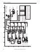

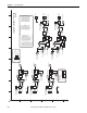
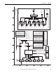

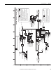
Table Of Contents
- PowerFlex 700S High Performance AC Drive - Phase II Control, Programming Manual
- Summary of Changes
- Table of Contents
- Preface
- Chapter 1 - Drive Start-Up
- Chapter 2 - Programming and Parameters
- Chapter 3 - Troubleshooting
- Appendix A - Human Interface Module Overview
- Appendix B - Application Notes
- Appendix C - Control Block Diagrams
- Appendix D - PowerFlex 700S Permanent Magnet Motor Specifications
- Appendix E - ATEX Approved PowerFlex 700S, Phase II Drives in Group II Category (2) Applications with ATEX Approved Motors
- Appendix F - History of Changes
- Index
- Back Cover
Rockwell Automation Publication 20D-PM001C-EN-P - July 2013 183
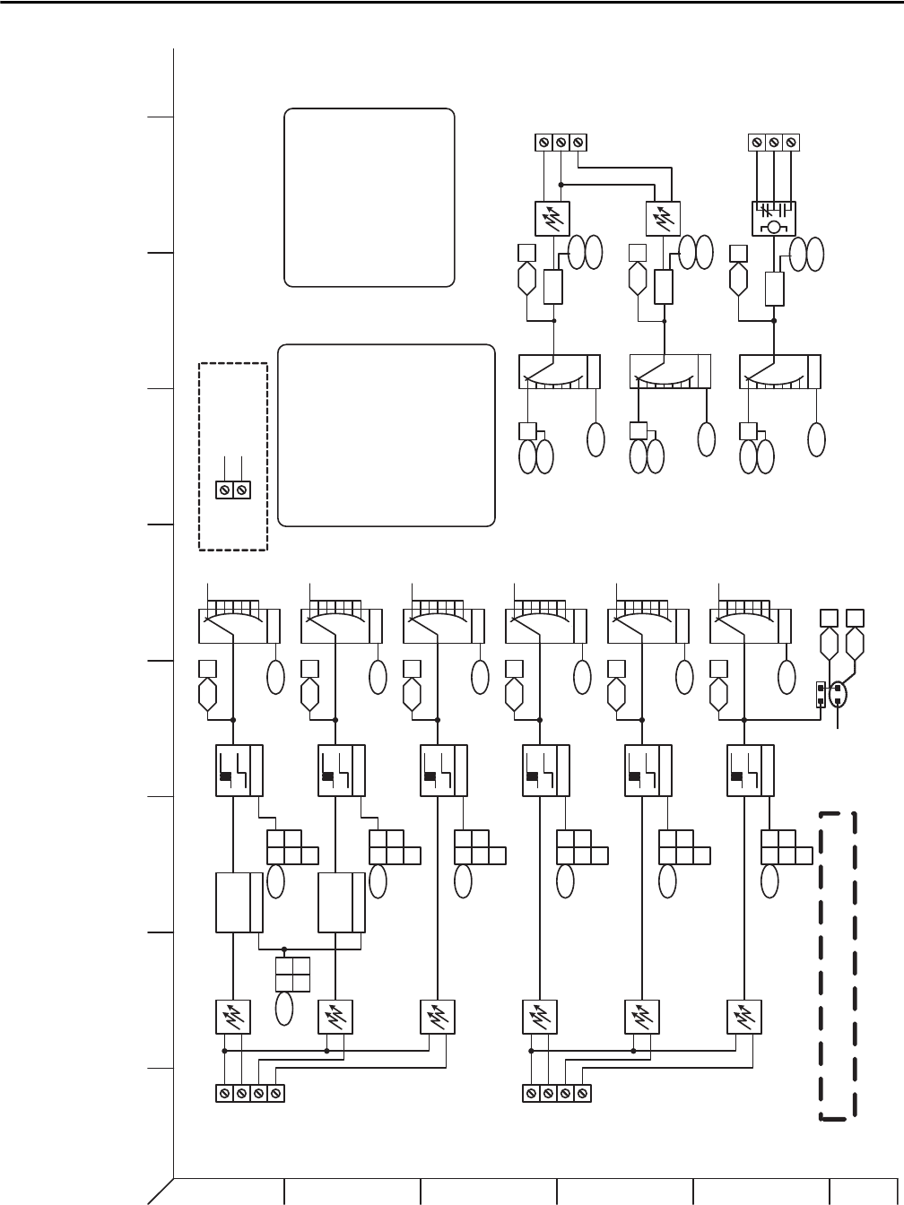
Control Block Diagrams Appendix C
Debounce
TB2-09
TB2-10
TB2-11
{DI 1-3 Common}
DigIn Debounce
Debounce
Debounce
SynchLink
Bit Filter
SynchLink
Bit Filter
236 08
Prt0/1 RegisCnfg
847
TB2-03
TB2-04
Dig Out2 Data
Dig Out2 Bit
Local I/O Status
(Dig Out 1)
Inputs & Outputs - Digital
(Task 1)
846
824 16
24 VDC
24 VDC CommonTB2-01
TB2-02
1
2
3
4
5
6
BA
D
C
FE HG
I
824 01
TB2-12
Selector
09
10 11
823 01 02
03 04
05
DigIn Debounce
823 06 07
08 09
10
DigIn Debounce
823 11 12
13 14
15
Debounce
DigIn Debounce
823 16 17
18 19
20
Debounce
DigIn Debounce
823 21 22
23 24
25
Debounce
DigIn Debounce
823 26 27
28 29
30
825
824 02
Selector
826
824 03
Selector
827
824 04
Selector
828
824 05
Selector
829
824 06
Selector
830
Local I/O Status
[DigIn 1]
Local I/O Status
[DigIn 2]
Local I/O Status
[DigIn 3]
Local I/O Status
[DigIn 4]
Local I/O Status
[DigIn 5]
Local I/O Status
[DigIn 6]
Dig In6 Sel
Dig In5 Sel
Dig In4 Sel
Dig In3 Sel
Dig In1 Sel
Dig In2 Sel
TB2-13
TB2-14
TB2-15
{DI 4-6 Common}
TB2-16
{Hw Enable}
852
Dig Out1 Data
Dig Out1 Bit
Local I/O Status
(Dig Out 2)
851
824 17
857
Rly Out3 Data
Rly Out3 Bit
Local I/O Status (Relay Out 3)
856
824 18
TB2-05
TB2-06
TB2-07
TB2-08
155 21
Logic Status
[Hw Enable On]
Bypass
Hw Enable
Jumper
When DI 6 is set for Hardware Enable ,
p830 is not available
824 00
Local I/O Status
[Hw Enbl Byps]
24vDC Inputs
24vDC / 115vAC Inputs
S4 - Open for 115vAC
Selector
845
850
855
Selector
Selector
Rly Out3 Sel
Dig Out1 Sel
Dig Out2 Sel
0) User Select
1) Not Fault
2) Not Alarm
3) Ready
4) Running
5) Reserved
6) Reserved
7) Enable On
8) Active
9) At Speed
10) At Setpt 1
11) Above Setpt2
12) At ZeroSpeed
13) Speed Limit
14) CurrentLimit
15) Torque Limit
16) Power Limit
17) Fault
18) Alarm
19) Command Dir
20) Actual Dir
21) Jogging
22) In Position
23) Posit Watch1
24) Posit Watch2
25) Cmpr 1 A </=B
26) Cmpr 1 A >/=B
27) Cmpr 2 A </=B
28) Cmpr 2 A >/=B
Digital Output Selections
Dflt = 3
Dflt = 8
Dflt = 1
0) Not Used
1) Enable
2) Clear Faults
3) Ext Fault
4) Norm Stop-CF
5) Start
6) Reverse
7) Run
8) Reserved
9) Reserved
10) Jog 1
11) Reserved
12) Reserved
13) Jog 2
14) Normal Stop
15) Spd Ref Sel0
16) Spd Ref Sel1
17) Spd Ref Sel2
18) CurLim Stop
19) Coast Stop
20) AccelDecel2
21) BscIndx Step
22) BscIndxStpRv
23) MOP Inc
24) MOP Dec
25) MOP Reset
26) PI Trim En
27) PI Tr im Hold
28) PI Trim Rst
29) Trend Trig
30) PreCharge En
31) Reserved
32) +Hrd OvrTrvl
3
3) -Hrd OvrTrvl
34) UserGen Sel0
35) UserGen Sel1
36) UserGen Sel2
37) UserGen Sel3
38) ExtFault Inv
39) Home Switch
40) Find Home
41) Return Home
Digital Input Selections
Delay
848
849
Dig Out1 On Time
Dig Out1 Off Time
Delay
853
854
Dig Out2 On Time
Dig Out2 Off Time
Delay
858
859
Rly Out On Time
Rly Out Off Time
in_out_digital.eps