
Instruction Manual
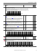
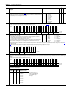
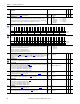
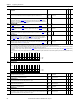
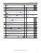
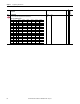
Table Of Contents
- PowerFlex 700S High Performance AC Drive - Phase II Control, Programming Manual
- Summary of Changes
- Table of Contents
- Preface
- Chapter 1 - Drive Start-Up
- Chapter 2 - Programming and Parameters
- Chapter 3 - Troubleshooting
- Appendix A - Human Interface Module Overview
- Appendix B - Application Notes
- Appendix C - Control Block Diagrams
- Appendix D - PowerFlex 700S Permanent Magnet Motor Specifications
- Appendix E - ATEX Approved PowerFlex 700S, Phase II Drives in Group II Category (2) Applications with ATEX Approved Motors
- Appendix F - History of Changes
- Index
- Back Cover

Rockwell Automation Publication 20D-PM001C-EN-P - July 2013 43
Programming and Parameters Chapter 2
153 Control Options
Set bits to configure the options for operating the drive. Note: Bit 3 “Flying Start” was added for firmware version 2.004. Bit 20, 21, and 29 were added for firmware version 3.001. Added bit 31 “Ids
Test Enable” for firmware version 4.001.
No. Name
Description
Values
Linkable
Read-Write
Data Type
Options
Ids Test Enable
Sys Inrt En
Slip Test En
PM Offset En
Pwr Diag En
Trq Trim En
MC Atune En
Time Axis En
PITrim EnOut
Reserved
Inrt TrqLPEn
Motor OL Ret
Slip Comp En
SpdRegPreset
Aux Pwr Sply
Auto Tach Sw
Reserved DM
Reserved DM
OL ClsLpDsbl
Jog -NoInteg
Iq Delay
Motor Dir
Reserved
3WireControl
Trq DsblZSpd
Trq StopRamp
Jog - NoRamp
Jog in Trq
Flying Start
SErrFilt1Stg
SRef LdLg En
Bipolar SRef
Default 000000000x1000000000000100001001
Bit 313029282726252423222120191817161514131211109876543210
Bit Name Current Function
0 Bipolar SRef When this bit is enabled a bipolar speed reference is used. In bipolar reference mode, Par 40 [Selected Spd Ref] indicates both the speed magnitude and the
direction: Positive speed reference values (+) = forward direction and negative speed reference values (–) = reverse direction. When this bit is disabled a
unipolar speed reference is used. In unipolar mode, the speed reference is limited to a minimum value of zero (0). In this case Par 40 [Selected Spd Ref]
supplies only the speed magnitude. The direction is determined by Par 152
[Applied LogicCmd] bits 20 “Forward” and 21 “Reverse”. The forward/reverse
direction button on the HIM is one possible source for the Applied Logic Command direction bits. The following chart explains the effect that the direction
button on the HIM has based on the condition of the “Bipolar SRef” bit:
Bipolar
Reference Controlled By HIM? HIM Direction Button
Enabled Yes Changes the motor direction due to a HIM supplied (+) or (-) command signal.
Enabled No Has no effect on motor direction. Direction determined by sign of Par 40 [Selected Spd Ref].
Disabled Yes Changes the motor direction due to a HIM supplied Forward or Reverse Logic Command bit.
Disabled No Changes the motor direction due to a HIM supplied Forward or Reverse Logic Command bit.
In either Bipolar or Unipolar mode, the selected direction can be determined from the sign of Par 41
[Limited Spd Ref]. Positive values indicate forward
rotation and negative values indicate reverse rotation.
1 SRef LdLg En Enables/disables the Speed Reference Lead Lag Filter
2 SErrFilt1Stg
Setting this bit will configure the speed error filter as a single first order low pass filter. Clearing this bit will configure the speed error filter as two cascaded
first order low pass filters
3 Flying Start Enables/disables the function which reconnects to a spinning motor at actual rpm when a start command is issued
4 Jog in Torq Overrides Par 110
[Speed/TorqueMode] setting when a jog command is received
5 Jog-NoRamp Bypasses the Speed Reference Ramp and S-Curve
6 Trq StopRamp Overrides Par 110 [Speed/TorqueMode] setting when stopping
7 Trq DsblZSpd Configures how the drive uses stop dwell time
8 3WireControl Configures the drive for 3-wire control
10 Motor Dir Changes direction of the motor rotation
11 Iq Delay Enables the Torque Current Delay option
12 Jog-NoInteg Configures the speed regulator’s integrator to “hold” when jogging
13 OL ClsLpDsbl Overload Closeloop Calculation Disable
14 Reserved DM Reserved for use by the Drive module for “Invert Speed Feedback”
15 Reserved DM Reserved for use by the Drive module for “Invert Motor Torque Current”
16 Auto Tach Sw Switches the drive to secondary motor feedback. This bit cannot be set when Par 485 [Motor Ctrl Mode] = 2 “PMag Motor”.
17 Aux Pwr Sply
Enables the use of an auxiliary power supply. When set to 1, the Main Control Board (MCB) examines internal 12V DC power to see when it is energized. When
set to 0, the MCB examines the voltage of the DC Bus. This bit enables the MCB to remain energized when 3-Ø voltage is de-energized.
18 SpdRegPreset When set to “1”, this bit selects Par 303
[Motor Torque Ref] for the Speed Regulator preset. When set to “0”, Par 87 [SReg Trq Preset] is selected.
19 Slip Comp Enables slip compensation
20 Motor OL Ret Enables motor over-load retention
21 Inrt TrqLPEn Enables the Inertia Compensation Torque Output Low Pass Filter
23 PITrim EnOut Enables the output of Process Trim
24 Time Axis En Ramps the output of the Time Function Generator
25 MC Atune En Enables Autotune tests
26 Trq Trim En Enables Torque Trim
27 Pwr Diag En Enables the Power Diagnostic test
28 PM Offset En Enables the Permanent Magnet Motor offset test
29 Slip Test En Enables the Slip Frequency Auto-Tune function
30 Sys Inrt En Enables the System Inertia test
31 Ids Test Enable Enables the flux producing (d-axis) current test for the Field Oriented Control (FOC) encoder mode
0 = False
1 = True