
Instruction Manual
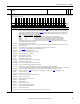
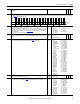
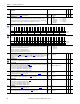
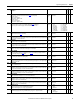
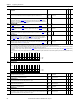
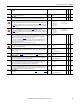
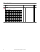
Table Of Contents
- PowerFlex 700S High Performance AC Drive - Phase II Control, Programming Manual
- Summary of Changes
- Table of Contents
- Preface
- Chapter 1 - Drive Start-Up
- Chapter 2 - Programming and Parameters
- Chapter 3 - Troubleshooting
- Appendix A - Human Interface Module Overview
- Appendix B - Application Notes
- Appendix C - Control Block Diagrams
- Appendix D - PowerFlex 700S Permanent Magnet Motor Specifications
- Appendix E - ATEX Approved PowerFlex 700S, Phase II Drives in Group II Category (2) Applications with ATEX Approved Motors
- Appendix F - History of Changes
- Index
- Back Cover
48 Rockwell Automation Publication 20D-PM001C-EN-P - July 2013
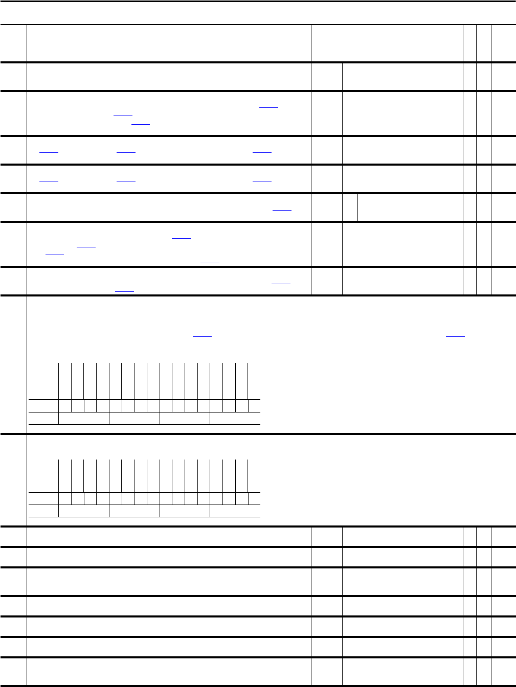
Chapter 2 Programming and Parameters
202 Time Axis Rate
Sets rate (1/sec) for the Time Function Generator to ramp from an output of 0 to 1 and from 1 to 0.
Default:
Min/Max:
Units:
1.0000
0.0100/20.0000
/s
Y
RW Real
203 Time Axis Output
The output of the Time Function Generator. When the Time Function Generator is enabled by Par 151 [Logic
Command] bit 3 “Time Axis En”, or Par 153
[Control Options], bit 24 “Time Axis En”, the value of this parameter
ramps from 0 to 1 at a rate determined by Par 202
[Time Axis Rate]. Conversely, when the Time Function Generator
is disabled, the value of this parameter ramps from 1 to 0.
Default:
Min/Max:
0.0000
0.0000/1.0000
RO Real
204 LimGen Y axis Mx
Sets Par 207 [Limit Gen Hi Out] and Par 208 [Limit Gen Lo Out] when the absolute value of Par 206 [LimGen X axis
In] is greater than or equal to 1.
Default:
Min/Max:
Units:
0.2500
0.0000/8.0000
P. U .
Y
RW Real
205 LimGen Y axis Mn
Sets Par 207 [Limit Gen Hi Out] and Par 208 [Limit Gen Lo Out] when the absolute value of Par 206 [LimGen X axis
In] is equal to 0.
Default:
Min/Max:
Units:
0.0500
0.0000/8.0000
P. U .
Y
RW Real
206 LimGen X axis In
The X axis input to the Limit Generator. Typically this parameter is linked to a speed reference or to Par 203 [Time
Axis Output].
Default:
Min/Max:
YY Y
RW Real
207 Limit Gen Hi Out
Displays the positive output of the Limit Generator. When Par 206 [Limit Gen X axis In] is greater than or equal to
1, this value equals Par 204
[Limit Gen Y axis Mx]. When Par 206 [Limit Gen X axis In] is equal to 0, this value
equals Par 205 [Limit Gen Y axis Mn]. For values of X Axis input between 0 and 1, the value of this parameter is
interpolated from Y axis min. and max. values. Typically it is linked to Par 188 [PI Integ HLim].
Default:
Min/Max:
Units:
8.0000
0.0000/8.0000
P. U .
RO Real
208 Limit Gen Lo Out
Displays the negative output of the Limit Generator. The value of this parameter is the negative of Par 207 [Limit
Gen Hi Out]. Typically it is linked to Par 189 [PI Integ LLim].
Default:
Min/Max:
Units:
-8.0000
-8.0000/0.0000
P. U .
RO Real
210 PeakDtct Ctrl In
Sets the configuration of the two peak/level detectors. Peak detection (when “set” and “hold” are off) causes the output to capture the peak min./max.
• Bit 2 “Peak1SelHigh” and bit 6 “Peak2SelHigh” determine if the peak/level detector is positive or negative. If the bit is set the detector detects positive peaks or levels above the preset. If the bit
is not set the detector detects "valleys" or levels below the preset. The output shows the min. or max. peak.
• Bit 0 “Peak 1 Set” bit is used to reset the output to the value in Par 214
[PeakDtct1 Preset] (default 0). Bit 4 “Peak 2 Set” bit is used to reset the output to the value in Par 218 [PeakDtct2 Preset]
(default 0).
• Bit 1“Peak 1 Hold” is used to hold the output at the present value in Par 214 [PeakDtct1 Preset]. Bit 5 “Peak 2 Hold” is used to hold the output at the present value in Par 218 [PeakDtct2 Preset].
211 PeakDtct Status
Status of peak/level detectors. A peak detector sets its “Change” bit for one scan when it detects a peak. The” Change” bit is off when set or when the “Hold” bit is on.
212 PkDtct1 In DInt
Integer input to the first peak/level detector.
Default:
Min/Max:
0
-/+2147483648
Y
RW 32-bit
Integer
213 PkDtct1 In Real
Floating point input to the first peak/level detector.
Default:
Min/Max:
0.0000
-/+2200000000.0000
Y
RW Real
214 PeakDtct1 Preset
The first detector (in set or hold modes) compares this value to its input for level detection. When the detector
trips (in set mode) it transfers the value of this parameter to its output.
Default:
Min/Max:
0.0000
-/+2200000000.0000
Y
RW Real
215 PeakDetect1 Out
Output from the first peak/level detector.
Default:
Min/Max:
0.0000
-/+2200000000.0000
RO Real
216 PkDtct2 In DInt
Integer input to second peak/level detector.
Default:
Min/Max:
0
-/+2147483648
Y
RW 32-bit
Integer
217 PkDtct2 In Real
Floating point input to second peak/level detector.
Default:
Min/Max:
0.0000
-/+2200000000.0000
Y
RW Real
218 PeakDtct2 Preset
The second detector (in set or hold modes) compares this value to its input for level detection. When the detector
trips (in set mode) it transfers the value of this parameter to its output.
Default:
Min/Max:
0.0000
-/+2200000000.0000
Y
RW Real
No. Name
Description
Values
Linkable
Read-Write
Data Type
Options
Reserved
Reserved
Reserved
Reserved
Reserved
Reserved
Reserved
Reserved
Reserved
Peak2SelHigh
Peak 2 Hold
Peak 2 Set
Reserved
Peak1SelHigh
Peak 1 Hold
Peak 1 Set
Default xxxxxxxxx0000000
Bit 1514131211109876543210
0 = False
1 = True
Options
Reserved
Reserved
Reserved
Reserved
Reserved
Reserved
Reserved
Reserved
Reserved
Reserved
Reserved
Reserved
Reserved
Reserved
Peak 2 Chng
Peak 1 Chng
Default xxxxxxxxxxxxxx00
Bit 1514131211109876543210
0 = False
1 = True