
Instruction Manual
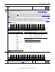
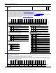
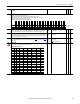
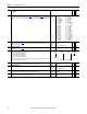
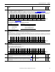
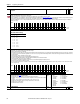
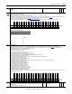
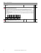
Table Of Contents
- PowerFlex 700S High Performance AC Drive - Phase II Control, Programming Manual
- Summary of Changes
- Table of Contents
- Preface
- Chapter 1 - Drive Start-Up
- Chapter 2 - Programming and Parameters
- Chapter 3 - Troubleshooting
- Appendix A - Human Interface Module Overview
- Appendix B - Application Notes
- Appendix C - Control Block Diagrams
- Appendix D - PowerFlex 700S Permanent Magnet Motor Specifications
- Appendix E - ATEX Approved PowerFlex 700S, Phase II Drives in Group II Category (2) Applications with ATEX Approved Motors
- Appendix F - History of Changes
- Index
- Back Cover
Rockwell Automation Publication 20D-PM001C-EN-P - July 2013 51
Programming and Parameters Chapter 2
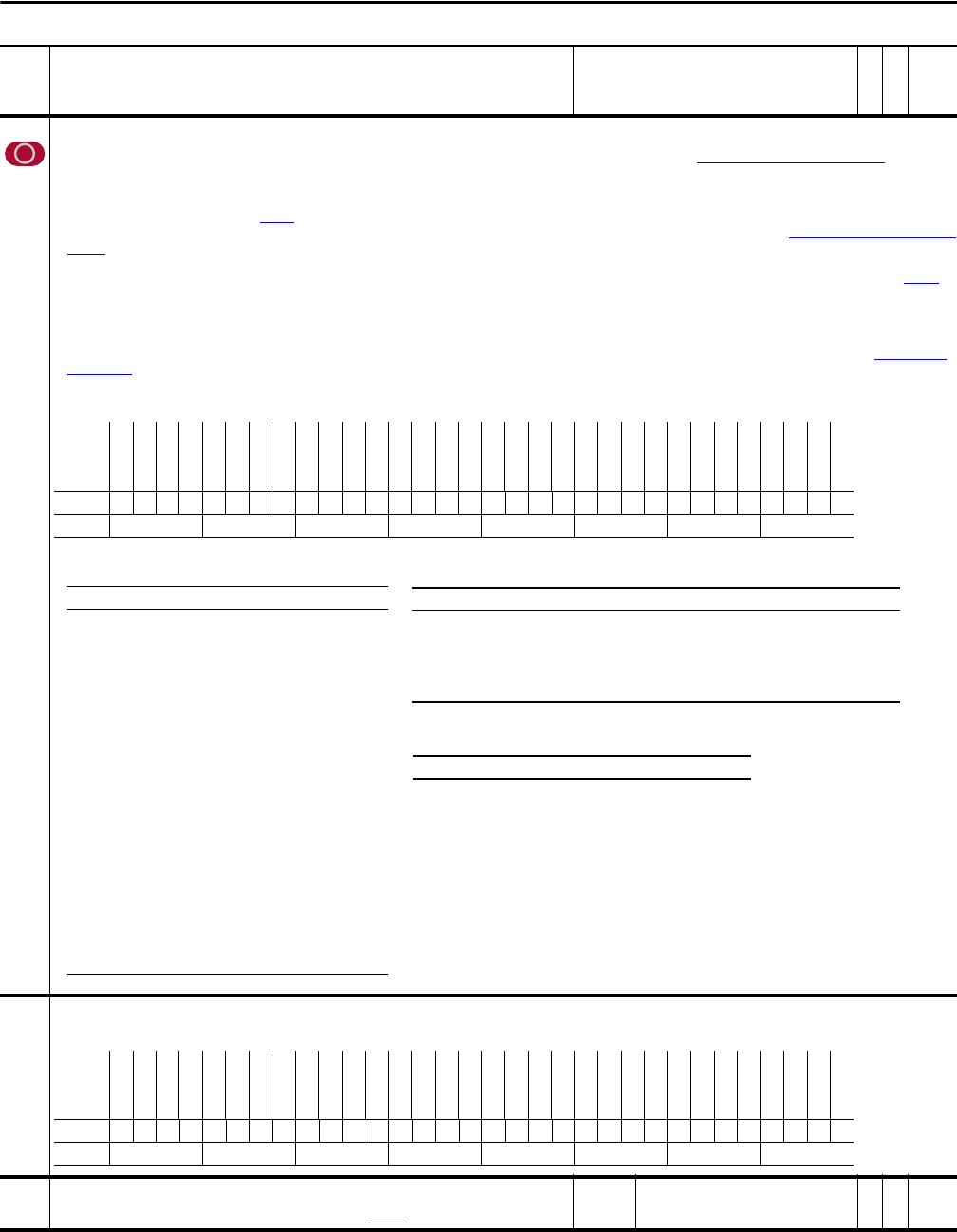
233 Encdr 0/1 Config
Specifies the configuration options for the encoder 0 and encoder 1.
• Bits 0 “Enc0 Filt bt0” through 3 “Enc0 Filt bt3”, or Bits 16 “Enc1 Filt bt0” through 19 “Enc1 Filt bt3” configure the encoder input filter (see Table 233A: Encoder Input Filter Settings
). The filter
requires the input signal to be stable for the specified time period. Input signal transitions within the filter time setting will be ignored. Bits 0-3 and 16-19 add 100ns filtering per stage to
encoder inputs.
• Bits 4 “Enc0 4x” and 5 “Enc0 A Phs” or 20 “Enc1 4x” and 21”Enc1 A Phs” determine how the encoder channel A and B signals will be interpreted. Typically, both encoder phases A and B are used
so that direction information is available. Par 230
[Encdr0 Position] counts up for forward rotation and down for reverse rotation. If bit 5 is set, then the B phase signal is ignored. As a result, the
encoder position will only increase, regardless of rotation direction. Bits 4 and 5 together also determine the number of edges counted per encoder pulse (see Table 233B: Multiplier and Direction
Settings). “4x” sampling counts both rise and fall of both A and B encoder phases, hence 4 edges per pulse. In 4x mode, the encoder position will change by four times the encoder pulses per
revolution rating (PPR) per encoder revolution (e.g., it increments the value in Par 230 [Encdr0 Position] by 4096 for one revolution of a 1024 PPR encoder).
• Bit 6 “Enc0 Dir” and 22 “Enc1 Dir” inverts the channel A input, thus reversing the direction of the feedback. Note that changes in encoder direction (bit 6 or 22) may require changing Par 153
[Control Options] bit 10 “Motor Dir”.
• Bit 7 “Enc0 EdgTime” or bit 23 “Enc1 EdgTime” configures the method of sampling used by the Velocity Position Loop (VPL). Setting the bit chooses "Edge to Edge" sampling, while resetting the
bit to zero selects "Simple Difference" sampling. "Simple Difference" sampling calculates speed by examining the difference between pulse counts over a fixed sample time. "Edge to Edge"
sampling adjusts the sample time to synchronize with the position count updates from the daughter card - improving the accuracy of the speed calculation.
• Bits 10 “En0SmplRate bt0” through 12 “En0SmplRate bt2” or bits 26 “En1SmplRate bt0” through 28 “En1SmplRate bt2” configure the Finite Impulse Response (FIR) Filter (see Table 233C: FIR
Filter Settings). This setting reduces the effect of noisy feedback on the system. Refer to the “Speed/Position Feedback” section of the PowerFlex® 700S with Phase II Control Reference Manual,
publication PFLEX-RM003 for details.
Note: Bit 27 is set to 0 = False by default for firmware version 1.11 and is set to 1 = True by default for firmware version 2.003.
234 Encdr 0/1 Error
Indicates the error status of the encoder 0 and encoder 1.
Note: Bit 4 was changed to “Reserved” for firmware version 2.004.
235 RegisLtch0 Value
Displays the registration data of port 0. Indicates the position reference counter value latched by the external
strobes. The strobe signal used to trigger the latch is configurable by Par 236
[RegisLtch 0/1 Cnfg].
Default:
Min/Max:
0
-/+2147483648
RW 32-bit
Integer
No. Name
Description
Values
Linkable
Read-Write
Data Type
Options
Reserved
Reserved
Reserved
En1SmplRt b2
En1SmplRt b1
En1SmplRt b0
Reserved
Reserved
Enc1 EdgTime
Enc1 Dir
Enc1 A Phs
Enc1 4x
Enc1 Filt b3
Enc1 Filt b2
Enc1 Filt b1
Enc1 Filt b0
Reserved
Reserved
Reserved
En0SmplRt b2
En0SmplRt b1
En0SmplRt b0
Reserved
Reserved
Enc0 EdgTime
Enc0 Dir
Enc0 A Phs
Enc0 4x
Enc0 Filt b3
Enc0 Filt b2
Enc0 Filt b1
Enc0 Filt b0
Default xxx011xx10011010xxx011xx10011010
Bit 313029282726252423222120191817161514131211109876543210
0 = False
1 = True
Table 233A: Encoder Input Filter Settings
Bit 3/19 2/18 1/17 0/16 Encoder Bit Filter Settings
0000Filter disabled
0001100 ns filter
0010200 ns filter
0011300 ns filter
0100400 ns filter
0101500 ns filter
0110600 ns filter
0111700 ns filter
1000800 ns filter (default setting)
1001900 ns filter
10101000 ns filter
10111100 ns filter
11001200 ns filter
11011300 ns filter
11101400 ns filter
11111500 ns filter
Table 233B: Multiplier and Direction Settings
Bit 5/21 4/20 Mult Directions Comments
0 0 2x fwd/rev Counts rise/fall of phase A, phase B only used to find direction
0 1 4x fwd/rev Counts rise/fall of both A and B phases (default setting)
1 0 1x fwd only Counts rise of phase A. Phase B ignored.
1 1 2X fwd only Counts rise of phase A. Phase B ignored.
Table 233C: FIR Filter Settings
Bit 12/28 11/27 10/26 Taps
0001
0012
0104
0118
10016
10132
11064
111127
Options
Reserved
Reserved
Reserved
Reserved
Reserved
Reserved
Reserved
Reserved
Reserved
Reserved
Reserved
Reserved
Enc1 PhseLev
Enc1 PhseLos
Enc1 QuadLos
Enc1 Missing
Reserved
Reserved
Reserved
Reserved
Reserved
Reserved
Reserved
Reserved
Reserved
Reserved
Reserved
Reserved
Enc0 PhseLev
Enc0 PhseLos
Enc0 QuadLos
Enc0 Missing
Default xxxxxxxxxxxx0000xxxxxxxxxxxx0000
Bit 313029282726252423222120191817161514131211109876543210
0 = False
1 = True