
Instruction Manual
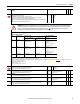
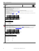
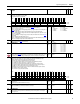
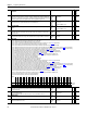
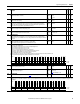

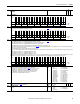
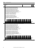
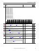
Table Of Contents
- PowerFlex 700S High Performance AC Drive - Phase II Control, Programming Manual
- Summary of Changes
- Table of Contents
- Preface
- Chapter 1 - Drive Start-Up
- Chapter 2 - Programming and Parameters
- Chapter 3 - Troubleshooting
- Appendix A - Human Interface Module Overview
- Appendix B - Application Notes
- Appendix C - Control Block Diagrams
- Appendix D - PowerFlex 700S Permanent Magnet Motor Specifications
- Appendix E - ATEX Approved PowerFlex 700S, Phase II Drives in Group II Category (2) Applications with ATEX Approved Motors
- Appendix F - History of Changes
- Index
- Back Cover
Rockwell Automation Publication 20D-PM001C-EN-P - July 2013 61
Programming and Parameters Chapter 2
278 Sleep-Wake Mode
Enables/disables the Sleep-Wake function.
Important: When enabled, the following conditions must be met:
• A proper value must be programmed for parameters 280 [Wake Level] and 282 [Sleep Level].
• A speed reference must be selected in parameter 27 [Speed Ref A Sel].
• At least one of the following must be programmed (and input closed) in [Dig Inx Sel]; “Enable,” “Stop=CF,”
“Run.”
Note: This parameter was added with firmware version 5.002.
Default:
Options:
0 =
0 =
1 =
2 =
“Disabled”
“Disabled”
“Direct”
“Invert”
279 Sleep-Wake Ref
Selects the source of the input controlling the Sleep-Wake function.
Note: This parameter was added with firmware version 5.002.
Default:
Options:
2 =
1 =
2 =
“Analog In 2”
“Analog In 1”
“Analog In 2”
280 Wake Level
Defines the analog input level (at or above) that will start the drive.
Note: This parameter was added with firmware version 5.002.
Default:
Min/Max:
Units:
6.000 mA, 6.000V
[Sleep Level]/20.000 mA, 10.000V
0.001 mA / 0.001V
RW Real
281 Wake Time
Defines the amount of time that the value of [Wake Level] must be present before a Start is issued.
Note: This parameter was added with firmware version 5.002.
Default:
Min/Max:
Units:
0.0 s
0.0/1000.0 s
0.1 s
RW Real
282 Sleep Level
Defines the analog input level (at or below) that will stop the drive.
Note: This parameter was added with firmware version 5.002.
Default:
Min/Max:
Units:
5.000 mA / 5.000V
4.000 mA, 0.000V / [Wake Level]
0.001 mA / 0.001V
RW Real
283 Sleep Time
Defines the amount of time that the value of [Sleep Level] must be present before a Stop is issued.
Note: This parameter was added with firmware version 5.002.
Default:
Min/Max:
Units:
0.0 s
0.0/1000.0 s
0.1 s
RW Real
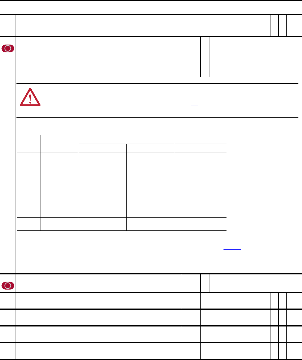
No. Name
Description
Values
Linkable
Read-Write
Data Type
ATTENTION: Enabling the Sleep-Wake function can cause unexpected machine operation during the Wake mode. Equipment damage
and/or personal injury can result if parameter 278 [Sleep-Wake Mode] is used in an inappropriate application. Do Not use this function
without considering the information below and in Sleep-Wake Mode on page 171
. In addition, all applicable local, national and
international codes, standards, regulations or industry guidelines must be considered.
Conditions Required to Start Drive
(1)(2)(3)
(1) When power is cycled, if all of the above conditions are present after power is restored, restart will occur.
(2) If all of the above conditions are present when [Sleep-Wake Mode] is “enabled,” the drive will start.
(3) The active speed reference is determined as explained in “Reference Selection” in the PowerFlex 700S AC Drives Phase II Control Reference Manual, publication PFLEX-RM003
. The Sleep-Wake function and the speed
reference may be assigned to the same input.
(4) Command must be issued from HIM, TB or network.
(5) Run Command must be cycled.
(6) Signal does not need to be greater than wake level.
Input After Power-Up After a Drive Fault After a Stop Command
Reset by Stop-CF, HIM or TB Reset by Clear Faults (TB) HIM or TB
Stop Stop Closed
Wake Signal
Stop Closed
Wake Signal
New Start or Run Cmd.
(4)
Stop Closed
Wake Signal
Stop Closed
Direct Mode
Analog Sig. > Sleep Level
(6)
Invert Mode
Analog Sig. < Sleep Level
(6)
New Start or Run Cmd.
(4)
Enable Enable Closed
Wake Signal
(4)
Enable Closed
Wake Signal
New Start or Run Cmd.
(4)
Enable Closed
Wake Signal
Enable Closed
Direct Mode
Analog Sig. > Sleep Level
(6)
Invert Mode
Analog Sig. < Sleep Level
(6)
New Start or Run Cmd.
(4)
Run New Run Cmd.
(5)
Wake Signal
New Run Cmd.
(5)
Wake Signal
New Run Cmd.
(5)
Wake Signal
New Run Cmd.
(5)
Wake Signal