
Instruction Manual
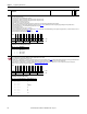
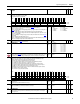
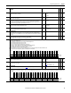

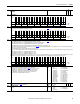
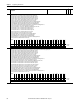
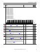
Table Of Contents
- PowerFlex 700S High Performance AC Drive - Phase II Control, Programming Manual
- Summary of Changes
- Table of Contents
- Preface
- Chapter 1 - Drive Start-Up
- Chapter 2 - Programming and Parameters
- Chapter 3 - Troubleshooting
- Appendix A - Human Interface Module Overview
- Appendix B - Application Notes
- Appendix C - Control Block Diagrams
- Appendix D - PowerFlex 700S Permanent Magnet Motor Specifications
- Appendix E - ATEX Approved PowerFlex 700S, Phase II Drives in Group II Category (2) Applications with ATEX Approved Motors
- Appendix F - History of Changes
- Index
- Back Cover
62 Rockwell Automation Publication 20D-PM001C-EN-P - July 2013
Chapter 2 Programming and Parameters
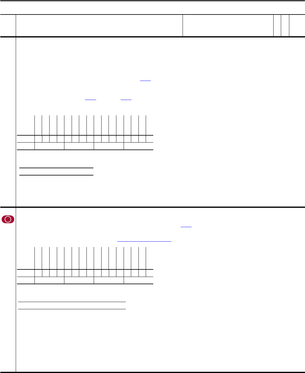
284 Sleep Control
Status of the Sleep-Wake function.
• Bit 0 “Enable” when set, Sleep-Wake mode is enabled.
• Bit 1 “Analog Ref 0” when set, indicates that analog input 1 is used for Sleep mode control.
• Bit 2 “Analog Ref 1” when set, indicates that analog input 2 is used for Sleep mode control.
• Bit 3 “Mode 0” when set, direct control is used.
• Bit 4 “Mode 1” when set, inverted control is used.
• Bits 5…7 “State x” indicate the Sleep-Wake mode state that is currently active. See Table 284A: Sleep-Wake Mode Active State below.
• Bit 8 “Digin Cnflct” when set indicates that a digital input conflict exists. See Par Par 278
[Sleep-Wake Mode] for details on digital input programming for the Sleep-Wake function.
• Bit 9 “Stop Latch” when set, a Stop command is being issued from the sleep mode.
• Bit 10 “Start Latch” Not used.
• Bit 11 “Not Running” when set, the drive is not running.
• Bit 12 “Level Cnflct” when set, the value of Par 280
[Wake Level] or Par 282 [Sleep Level] is outside the Min/Max range of the assigned analog input (mA or V). Or, if in direct mode, the value of
[Sleep Level] is greater than the value of [Wake Level].
Note: This parameter was added with firmware version 5.002.
285 Linear1 Config
Used to configure a linear encoder when a Multi Device Interface (MDI) feedback card is installed.
Note: This parameter was added for firmware version 2.003.
• Bit 5 “Direction” - Setting this bit to “1” inverts the count (up/down) direction of the linear feedback position Par 252 [FB Opt1 Posit]. If [FB Opt1 Posit] has been counting up for forward feedback
sensor travel then setting this bit will cause [FB Opt1 Posit] to count down. The opposite behavior will occur when the sensor moves in the other direction.
• Bit 6 “Stahl Linear” - Setting this bit to “1” indicates to the MDI card that a Stahl type linear device is being used. It this bit is set to “0” then a Temposonics linear device is being used.
• Bits 10 - 12 form a 3 bit moving average filter sampling rate. See Table 285A: Sample Rate Bit Settings
.
No. Name
Description
Values
Linkable
Read-Write
Data Type
Options
unused 3
unused 2
unused 1
Level Cnflct
Not Running
Start Latch
Stop Latch
Digin Cnflct
State 2
State 1
State 0
Mode 1
Mode 0
Analog Ref 1
Analog Ref 0
Enable
Default xxx0000000000000
Bit 1514131211109 8 7 6 5 4 3 2 1 0
0 = False
1 = True
Table 284A: Sleep-Wake Mode Active State
Bit 7 6 5 Active Mode
0 0 0 Drive is powering up
0 0 1 Drive is asleep
0 1 0 Drive is waiting
011Drive is awake
Options
Reserved
Reserved
Reserved
Op1SmplRt b3
Op1SmplRt b2
Op1SmplRt b1
Reserved
Reserved
Reserved
Stahl Linear
Direction
Reserved
Reserved
Reserved
Reserved
Reserved
Default xxx011xxx00xxxxx
Bit 1514131211109 8 7 6 5 4 3 2 1 0
0 = False
1 = True
Table 285A: Sample Rate Bit Settings
Bit 12 11 10 Exponent Value ‘n’ Filter Sample Size = 2
n
0000 1
0011 2
0102 4
0113 8 (Default)
1004 16
1015 32
1106 64
1 1 1 7 127