
Instruction Manual
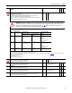
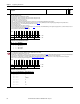
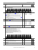
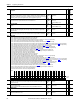
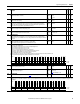

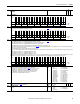
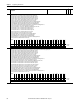
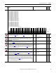
Table Of Contents
- PowerFlex 700S High Performance AC Drive - Phase II Control, Programming Manual
- Summary of Changes
- Table of Contents
- Preface
- Chapter 1 - Drive Start-Up
- Chapter 2 - Programming and Parameters
- Chapter 3 - Troubleshooting
- Appendix A - Human Interface Module Overview
- Appendix B - Application Notes
- Appendix C - Control Block Diagrams
- Appendix D - PowerFlex 700S Permanent Magnet Motor Specifications
- Appendix E - ATEX Approved PowerFlex 700S, Phase II Drives in Group II Category (2) Applications with ATEX Approved Motors
- Appendix F - History of Changes
- Index
- Back Cover

64 Rockwell Automation Publication 20D-PM001C-EN-P - July 2013
Chapter 2 Programming and Parameters
299 Elapsed MWHrs
Displays the total energy the drive has consumed or produced. Calculated from the absolute magnitude of the
product of motor speed and motor torque (power), accumulated over time. This value will increase in both regen
and motoring modes of operation. This parameter value can be changed (written to) by the user.
Default:
Min/Max:
Units:
Scale:
0.0
0.0/429496736.0
MWhr
x 10
RW 32-bit
Integer
300 Motor Spd Fdbk
Displays measured motor speed information from the selected feedback device.
Default:
Min/Max:
Units:
Scale:
0.0000
-/+14112.0000
rpm
Par 4
[Motor NP RPM] = 1.0 P.U.
RO Real
301 Motor Speed Ref
Displays the speed reference value, after the limit function. This is the input to the error calculator and speed
regulator.
Default:
Min/Max:
Units:
Scale:
0.0000
-/+14112.0000
rpm
Par 4
[Motor NP RPM] = 1.0 P.U.
RO Real
302 Spd Reg PI Out
Displays the output of the speed regulator. This is the input to torque control. A value of 1.0 represents base
torque of the motor.
Default:
Min/Max:
Units:
0.0000
-/+8.0000 P.U.
P. U .
RO Real
303 Motor Torque Ref
Displays the reference value of motor torque. The actual value of the motor torque is within 5% of this value.
Default:
Min/Max:
Units:
0.0000
-/+8.0000 P.U.
P. U .
RO Real
304 Limit Status
Displays the limit status of conditions that may be limiting the current reference or torque reference.
• Bit 0 “+MCS Iq Lim” indicates that torque producing current is at its positive limit.
• Bit 1 “+MCS Ws Lim” indicates that flux producing torque is at its positive limit.
• Bit 2 “0 Ia from +” indicates that torque producing current is limited to zero from the positive direction - refer to Par 353
[Iq Actual Lim].
• Bit 3 “+Iq Calc” indicates the calculation for torque producing current has reached its positive limit.
• Bit 4 “+Current Lim” indicates that the current reference has reached the positive Motor Current Limit set by Par 356 [Mtr Current Lim].
• Bit 5 “+DriveProtOL” indicates that the current reference has reached the positive current limit set by the Open Loop Inverter Overload, shown in Par 343
[OL OpnLp CurrLim].
• Bit 6 “+DriveProtCL” indicates that the current reference has reached the positive current limit set by the Closed Loop Inverter Overload, shown in Par 344 [OL ClsLp CurrLim].
• Bit 8 “+Torq Limit” indicates that the torque reference has reached the Positive Torque Limit set by Par 125
[Torque Pos Limit].
• Bit 9 “Mtrng PwrLim” indicates that the torque reference is being limited by the Motoring Power Limit set by Par 127 [Mtring Power Lim].
• Bit 10 “+Torq CurLim” indicates that current reference has reached the Actual Torque Producing Current Limit set by Par 353 [Iq Actual Lim].
• Bit 11 “Atune Tq Lim” indicates that the torque reference is being limited by Par 129
[Atune Trq Ref ].
• Bit 12 “+0 Torq Ena” indicates that the torque reference is limited to zero because Par 157 [Logic Ctrl State] bit 9 “Torq Ref En” is off.
• Bit 13 “+0 Curr Ena” indicates that the current reference is limited to zero because Par 157 [Logic Ctrl State] bit 11 “CurrRef En” is off.
• Bit 14 “Speed Limit” indicates the collective status of all speed limitations.
• Bit 15 “Current Lim” indicates the collective status of all current limitations
• Bit 16 “-MCS Iq Lim” indicates that torque producing current is at its negative limit.
• Bit 17 “-MCS Ws Lim” indicates that flux producing torque is at its negative limit.
• Bit 18 “0 Ia from -” indicates that torque producing current is limited to zero from the negative direction - refer to Par 353
[Iq Actual Lim].
• Bit 19 “-Iq Calc’ indicates the calculation for torque producing current has reached its negative limit.
• Bit 20 “-Current Lim” indicates that the current reference has reached the negative Motor Current Limit set by Par 356
[Mtr Current Lim].
• Bit 21 “-DriveProtOL” indicates that the current reference has reached the negative current limit set by the Open Loop Inverter Overload, shown in Par 343 [OL OpnLp CurrLim].
• Bit 22 “-DriveProtCL” indicates that the current reference has reached the negative current limit set by the Closed Loop Inverter Overload, shown in Par 344 [OL ClsLp CurrLim].
• Bit 24 “-Torq Limit” indicates that the torque reference has reached the Negative Torque Limit set by Par 126
[Torque Neg Limit].
• Bit 25 “Regen PwrLim” indicates that the torque reference is being limited by the Regenerative Power Limit set by Par 128 [Regen Power Lim].
• Bit 26 “-Torq CurLim” indicates that current reference has reached the Actual Torque Producing Current Limit set by Par 353 [Iq Actual Lim].
• Bit 27 “Bus Reg Tq Lim” indicates the bus voltage regulator is active and limiting the regenerative torque.
• Bit 28 “-0 Torq Ena” indicates that the torque reference is limited to zero because Par 157
[Logic Ctrl State] bit 9 “Torq Ref En” is off.
• Bit 29 “-0 Curr Ena” indicates that the current reference is limited to zero because Par 157 [Logic Ctrl State] bit 11 “CurrRef En” is off.
• Bit 30 “Torque Limit” indicates the collective status of all torque limitations.
• Bit 31 “Power Limit” indicates the collective status of all power limitations.
305 Mtr Trq Curr Ref
Displays the torque current reference present at the output of the current rate limiter. 100% is equal to 1 per unit
(P.U.) rated motor torque.
Default:
Min/Max:
Units:
0.0000
-/+8.0000 P.U.
P. U .
RO Real
306 DC Bus Voltage
Displays measured bus voltage.
Note: The maximum value was increased from 1000.0000 to 1170.0000 for firmware version 3.001.
Default:
Min/Max:
Units:
0.0000
0.0000/1170.0000
V
RO Real
307 Output Voltage
Displays RMS line-to-line fundamental motor voltage. This data is averaged and updated every 50 milliseconds.
Default:
Min/Max:
Units:
0.00
0.00/3000.00
V
RO Real
308 Output Current
Displays measured RMS motor current.
Default:
Min/Max:
Units:
0.00
0.00/10000.00
A
RO Real
No. Name
Description
Values
Linkable
Read-Write
Data Type
Options
Power Limit
Torque Limit
-0 Curr Enbl
-0 Trq Enbl
Bus Reg Lim
-Trq CurLim
Regen PwrLim
-Trq Limit
SpdReg Open
-DriveProtCL
-DriveProtOL
-Current Lim
-Iq Calc
0 Iq from -
-MCS Ws Lim
-MCS Iq Lim
Current Lim
Speed Limit
+0 Curr Enbl
+0 Trq Enbl
Atun Trq Lim
+Trq CurLim
Mtrng PwrLim
+Trq Limit
+SpdReg Open
+DriveProtCL
+DriveProtOL
+Current Lim
+Iq Calc
0 Iq from +
+MCS Ws Lim
+MCS Iq Lim
Default 00000000000000000000000000000000
Bit 313029282726252423222120191817161514131211109876543210
0 = False
1 = True