
Instruction Manual
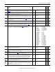
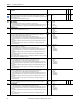
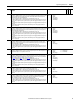
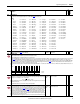
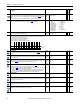
Table Of Contents
- PowerFlex 700S High Performance AC Drive - Phase II Control, Programming Manual
- Summary of Changes
- Table of Contents
- Preface
- Chapter 1 - Drive Start-Up
- Chapter 2 - Programming and Parameters
- Chapter 3 - Troubleshooting
- Appendix A - Human Interface Module Overview
- Appendix B - Application Notes
- Appendix C - Control Block Diagrams
- Appendix D - PowerFlex 700S Permanent Magnet Motor Specifications
- Appendix E - ATEX Approved PowerFlex 700S, Phase II Drives in Group II Category (2) Applications with ATEX Approved Motors
- Appendix F - History of Changes
- Index
- Back Cover
78 Rockwell Automation Publication 20D-PM001C-EN-P - July 2013
Chapter 2 Programming and Parameters
405 Dead Time Comp
The amount of voltage correction used to compensate for the loss of voltage during dead time. Do not adjust.
Contact factory for alternative settings.
Default:
Min/Max:
Units:
0
0/200
%
RW 16-bit
Integer
406 Power Loss Mode
Enter a value to configure the drive's response to a loss of input power, as sensed by an input voltage below the
value specified in Par 408
[Power Loss Level].
• Enter a value of “0” to make the drive fault and coast to a stop (supply no current to the motor) after the
amount of time specified in Par 407 [Power Loss Time] has expired.
• Enter a value of “2” to make the drive fault and continue "normal" operation after the amount of time
specified in Par 407 [Power Loss Time] has expired.
• Enter a value of “5” to make the drive provide only motor flux current during the power loss time.
Default:
Options:
0 =
0 =
1 =
2 =
“Coast”
“Coast” 3 = “Reserved”
“Reserved” 4 = “Reserved”
“Continue” 5 = “Flux Only”
407 Power Loss Time
Sets the amount of time that the drive will remain in a ride through condition before a fault is detected.
Default:
Min/Max:
Units:
2.0000
0.0000/60.0000
s
RW Real
408 Power Loss Level
Sets the percentage of the bus voltage at which ride-through begins and modulation ends. When the bus voltage
falls below this level and Par 406
[Power Loss Mode] is set to 0 “Coast” or 5 “Flux Only”, an alarm (F92 “Ride Thru”)
will be displayed on the HIM and the drive prepares for an automatic restart. Enter a percentage of the bus voltage
derived from the high voltage setting for the voltage class. For example: On a 400-480V drive,
Note: The definition was updated to include the bit settings for parameter 406 for firmware version 4.002.
Default:
Min/Max:
Units:
Scale:
22.1
15/95
%
0
RW 16-bit
Integer
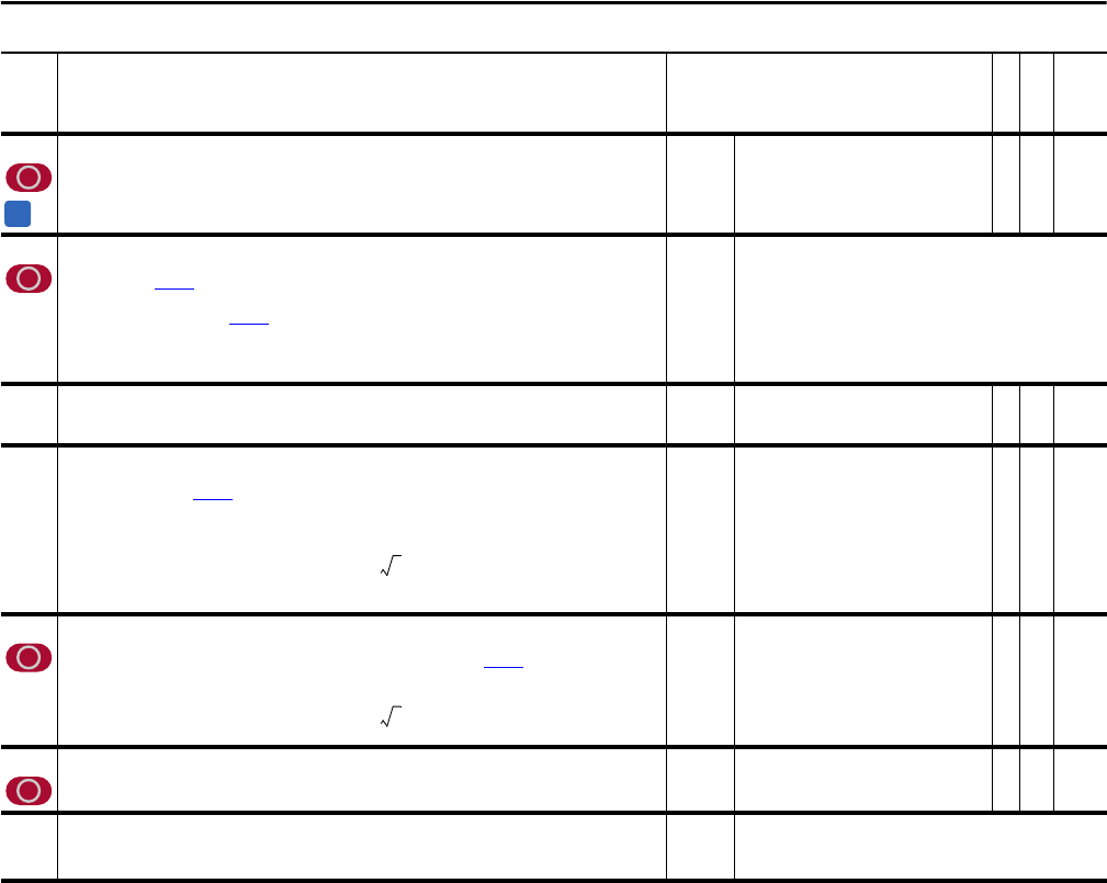
409 Line Undervolts
Controls the level of bus voltage that is needed to complete precharge and sets the level for undervoltage alarm/
fault detection. Enter a percentage of the bus voltage derived from the value in Par 401 [Rated Volts].
For example: on a 480V drive,
Default:
Min/Max:
Units:
61.5000
10.0000/90.0000
%
RW Real
410 PreChrg TimeOut
Sets the time duration of precharge. If bus voltage does not stabilize within this amount of time, a Precharge Error
exception event occurs.
Default:
Min/Max:
Units:
30.0000
10.0000/180.0000
s
RW Real
411 PreChrg Control
Must equal 1 to allow drive to exit precharge and begin to run. Link this parameter to a controller output word to
coordinate the precharge of multiple drives.
Default:
Options:
1 =
0 =
1 =
“Enbl PrChrg”
“Hold PrChrg”
“Enbl PrChrg”
No. Name
Description
Values
Linkable
Read-Write
Data Type
A
0.221 480Vac 2×× 150Vdc=
0.615 480Vac 2×× 418Vdc=