
Instruction Manual
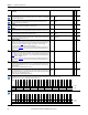

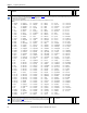
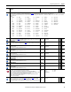
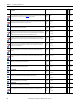
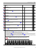
Table Of Contents
- PowerFlex 700S High Performance AC Drive - Phase II Control, Programming Manual
- Summary of Changes
- Table of Contents
- Preface
- Chapter 1 - Drive Start-Up
- Chapter 2 - Programming and Parameters
- Chapter 3 - Troubleshooting
- Appendix A - Human Interface Module Overview
- Appendix B - Application Notes
- Appendix C - Control Block Diagrams
- Appendix D - PowerFlex 700S Permanent Magnet Motor Specifications
- Appendix E - ATEX Approved PowerFlex 700S, Phase II Drives in Group II Category (2) Applications with ATEX Approved Motors
- Appendix F - History of Changes
- Index
- Back Cover
Rockwell Automation Publication 20D-PM001C-EN-P - July 2013 83
Programming and Parameters Chapter 2
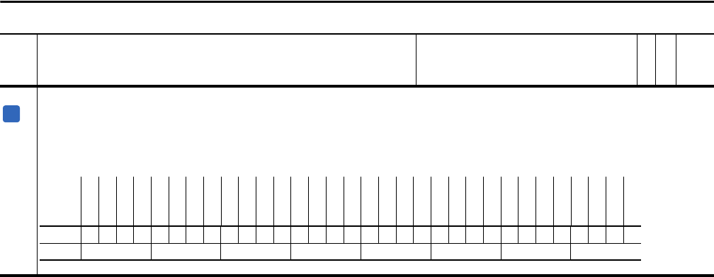
465 MC Diag Error 3
Displays the third diagnostic error encountered by the Motor Control (MC). Errors appear in this parameter in the order in which they occurred.
• Bit 9 “CurrSensor U” - indicates a current sensing fault in the U phase power structure of a frame 12 drive.
• Bit 11 “CurrSensor V” - indicates a current sensing fault in the V phase power structure of a frame 12 drive.
• Bit 13 “CurrSensor W” - indicates a current sensing fault in the W phase power structure of a frame 12 drive.
• Bit 17 “IFlux Range” - indicates that the Flux current is above 90% of the motor rated current.
Note: Bits 1 - 7, 10, 12 and 18 were changed to “Reserved”, bits 9, 11, 13 and 17 were changed for firmware version 3.001.
No. Name
Description
Values
Linkable
Read-Write
Data Type
A
Options
Reserved
Reserved
Reserved
Reserved
Reserved
Reserved
Reserved
Reserved
Reserved
Reserved
Reserved
Reserved
Reserved
Reserved
IFlux Range
Reserved
Reserved
Reserved
CurrSensor W
Reserved
CurrSensor V
Reserved
CurrSensor U
Reserved
Reserved
Reserved
Reserved
Reserved
Reserved
Reserved
Reserved
Reserved
Default xxxxxxxxxxxxxx0xxx0x0x0xxxxxxxxx
Bit 313029282726252423222120191817161514131211109876543210
0 = False
1 = True