Installation Instructions PowerFlex 750-Series Power Option Cabinets Topic Introduction Page Introduction 1 Additional Resources 2 What the Kits Contain 2 Bus-bar Selection Tables 4 Approximate Dimensions 8 Remove Power from All Equipment 10 Prepare for Installation 11 Lift the Empty Power Option Cabinet 11 Lift Loaded Power Option Cabinet 14 Calculate Total Lifting Weight of Cabinet 14 Accessory Kit Installation 14 Gasket Kit Installation 19 Drive Side Bus-bar Support Installati
PowerFlex 750-Series Power Option Cabinets Additional Resources The following table lists publications that provide general information on PowerFlex 750-Series drives.
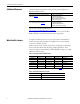
PowerFlex 750-Series Power Option Cabinets Table 3 - Optional Bus-bar and Bus-bar Accessory Kits Cat. No.
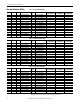
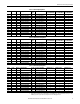
PowerFlex 750-Series Power Option Cabinets Bus-bar Selection Tables Power Frame LD Amps Catalog Number 315 315 355 400 450 450 560 630 710 800 850 900 1000 1400 8 8 8 8 8 8 9 9 9 9 9 9 10 10 540 585 612 750 796 832 1040 1090 1175 1465 1480 1600 1715 2330 Table 4 - 400 Volt Light Duty Drives Bus Bar Amps 975 975 975 975 975 975 1235 1235 1235 1625 1625 1625 2437 2437 20G1A‡C460JN0NNNNN 20G1A‡C540JN0NNNNN 20G1A‡C567JN0NNNNN 20G1A‡C650JN0NNNNN 20G1A‡C750JN0NNNNN 20G1A‡C770JN0NNNNN 20G11‡C910JN0NNNNN 20
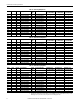
PowerFlex 750-Series Power Option Cabinets Table 7 - 480 Volt Light Duty Drives Power Frame LD Amps Catalog Number 400 450 500 600 650 700 800 900 1000 1100 1250 1350 1500 2000 8 8 8 8 8 8 9 9 9 9 9 9 10 10 485 545 590 710 765 800 960 1045 1135 1365 1420 1540 1655 2240 Bus Bar Amps 975 975 975 975 975 975 975 1235 1235 1625 1625 1625 2437 2437 20G1A‡D430AN0NNNNN 20G1A‡D485AN0NNNNN 20G1A‡D545AN0NNNNN 20G1A‡D617AN0NNNNN 20G1A‡D710AN0NNNNN 20G1A‡D740AN0NNNNN 20G11‡D800AN0NNNNN 20G11‡D960AN0NNNNN 20G11‡
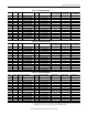
PowerFlex 750-Series Power Option Cabinets Table 10 - 600 Volt Light Duty Drives Power Frame LD Amps Catalog Number 350 400 450 500 500 550 700 800 900 950 1000 1100 1200 1500 8 8 8 8 8 8 9 9 9 9 9 9 10 10 355 395 435 460 510 545 690 760 835 900 980 1045 1220 1530 Bus Bar Amps 975 975 975 975 975 975 975 975 975 975 1235 1235 1235 1625 20G1A‡E295AN0NNNNN 20G1A‡E355AN0NNNNN 20G1A‡E395AN0NNNNN 20G1A‡E435AN0NNNNN 20G1A‡E460AN0NNNNN 20G1A‡E510AN0NNNNN 20G11‡E595AN0NNNNN 20G11‡E630AN0NNNNN 20G11‡E760AN0N
PowerFlex 750-Series Power Option Cabinets Table 13 - 690 Volt Light Duty Drives Power Frame LD Amps Catalog Number 315 355 400 450 500 530 630 710 800 850 900 1000 1100 1500 8 8 8 8 8 8 9 9 9 9 9 9 10 10 330 370 410 460 500 530 650 710 790 860 960 1020 1150 1485 Bus Bar Amps 975 975 975 975 975 975 975 975 975 975 975 1235 1235 1625 20G1A‡F265AN0NNNNN 20G1A‡F330AN0NNNNN 20G1A‡F370AN0NNNNN 20G1A‡F415AN0NNNNN 20G1A‡F460AN0NNNNN 20G1A‡F500AN0NNNNN 20G11‡F590AN0NNNNN 20G11‡F650AN0NNNNN 20G11‡F710AN0NNN
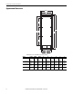
PowerFlex 750-Series Power Option Cabinets Approximate Dimensions Width A F Height D F B F E C Dimensions are in millimeters and (inches). Cat. No. 20-750-PBAY-66 20-750-PBAY-68 20-750-PBAY-86 20-750-PBAY-88 8 Height 2265.5 (89.2) 2265.5 (89.2) 2265.5 (89.2) 2265.5 (89.2) Width 600 (23.6) 600 (23.6) 800 (31.5) 800 (31.5) Depth 600 (23.6) 800 (31.5) 600 (23.6) 800 (31.5) A 520 (20.5) 520 (20.5) 720 (28.3) 720 (28.3) B 2205.5 (86.8) 2205.5 (86.8) 2205.5 (86.8) 2205.5 (86.
PowerFlex 750-Series Power Option Cabinets Width A F F Height D B F F E C Dimensions are in millimeters and (inches). Cat. No. 20-750-PBAY-126 20-750-PBAY-128 Height 2265.5 (89.2) 2265.5 (89.2) Width 1200 (47.2) 1200 (47.2) Depth 600 (23.6) 800 (31.5) A 1120 (44.1) 1120 (44.1) B 2205.5 (86.8) 2205.5 (86.8) Rockwell Automation Publication 750-IN030B-EN-P - October 2014 C 1042.3 (41.0) 1042.3 (41.0) D 1963.7 (77.3) 1963.7 (77.3) E 978.1 (38.5) 978.1 (38.5) F 452.5 (17.8) 452.5 (17.
PowerFlex 750-Series Power Option Cabinets Remove Power from All Equipment Remove power from all energized equipment before proceeding with these instructions. Refer to the product’s installation instructions and review all safety precautions before performing work on this equipment. PowerFlex 755 Drive ATTENTION: To avoid an electric shock hazard, verify that the voltage on the bus capacitors has discharged completely before servicing.
PowerFlex 750-Series Power Option Cabinets Prepare for Installation 1. Position the PowerFlex 755 drive in its desired location. IMPORTANT Determine the final installation location for the assembly before beginning joining procedures. The drive cabinet and power option cabinet should be assembled in this final position. Joined cabinets cannot be moved as a unit.
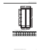
PowerFlex 750-Series Power Option Cabinets Release Power Option Cabinet from Shipping Skid Remove the power option cabinet from the shipping skid before installing busbar kits and other equipment. IMPORTANT The shipping skid is designed to support an empty cabinet only. It is not rated to support a loaded cabinet. 1. Remove the M8 hex bolts fastening a vertically oriented power option cabinet to the shipping skid. 2. Attach lifting hardware observing the rigging geometry illustrated below.
PowerFlex 750-Series Power Option Cabinets 3. Lift the empty cabinet off the shipping skid.
PowerFlex 750-Series Power Option Cabinets Lift Loaded Power Option Cabinet Power option cabinets are fitted with eye bolts for connecting lifting hardware. Do not exceed the maximum cabinet weight when using these lifting points. Refer to Calculate Total Lifting Weight of Cabinet on page 14. ATTENTION: To guard against equipment damage, calculate the total weight of the loaded power option cabinet. The combined cabinet and component weight must not exceed the maximum weight listed in Table 16.
PowerFlex 750-Series Power Option Cabinets Adhesive Overlay Label Apply the adhesive overlay label for a uniform appearance of the cabinet lineup. IMPORTANT Complete any planned modifications to the door before you apply the label. 1. Trim the label to fit the cabinet. Enclosure Width 600 mm 800 mm 1200 mm Label Width 578 mm 778 mm 2 x 578 mm 2. Remove the protective backing from the adhesive overlay label. 3.
PowerFlex 750-Series Power Option Cabinets Door Handle Install the door handle after final positioning of the cabinet to help avoid damage during transport. 1. Align the handle on the outside of cabinet door. 2. Pass the screws through the clearance holes and thread into the handle. 3. Tighten screws. 10-32 x 3/8 in.
PowerFlex 750-Series Power Option Cabinets Barrier Panels • Barrier panels are only required when joining a power option cabinet to a drive cabinet. • Barrier panels seal the wireway and bus-bar cabinet access openings on the side of the power option cabinet to be joined with the drive cabinet. • Barrier panels help maintain cooling air flow through the drive cabinet. IMPORTANT If barrier panels are not installed, an over temperature condition may result and cause nuisance tripping of the drive. 1.
PowerFlex 750-Series Power Option Cabinets Modify Barrier Panels for Bus-bar or Wire Passage After the power option cabinet and drive cabinet are joined, the barrier panels must be modified in order to pass bus work or power wiring between cabinets. Take care to only remove enough material to allow bus work or cabling to pass through. It is important to maintain as much seal as possible.
PowerFlex 750-Series Power Option Cabinets Gasket Kit Installation The adhesive backed gasket kit is available to provide a seal between cabinets when an IP54, NEMA 12 enclosure rating is required. ATTENTION: If the gasket material is applied to the cabinet prior to shipment to the installation site, protect the gasket from damage. If the gasket material is damaged, the integrity of the seal can be lost. Table 18 - Contents 20-750-PBAY-IP54 Gasket Kit Description Adhesive backed foam gasket tape Part No.
PowerFlex 750-Series Power Option Cabinets Figure 2 - 600 mm (23.6 in.) Deep Cabinet 12 (0.5) 98 (3.9) 504 (19.8) 4.5 (0.2) 381 (15.0) Top Corner Seam Detail 106 (4.2) 2206 (86.9) 1991 (78.4) 58 (2.3) 25 (1.
PowerFlex 750-Series Power Option Cabinets Figure 3 - 800 mm (31.5 in.) Deep Cabinets 12 (0.5) 298 (11.7) 704 (27.7) 381 (15.0) 4.5 (0.2) Top Corner Seam Detail 109 (4.3) 2206 (86.9) 1984 (78.1) 62 (2.4) 25 (1.
PowerFlex 750-Series Power Option Cabinets Drive Side Bus-bar Support Installation Drive side bus-bar kits are used with right side power option cabinets only. DC Input Drive Side Bus-bar Supports Table 19 - 20-750-PBAY-INS-2 Kit Contents Description DC Bus-bar Support M8 x 22 Hexalobular Screw M8 Lock Washer M8 Flat Washer Part No. PN-181183 419062-5HKL 419064-100SK 419064-1SK Quantity 1 3 3 3 1. Fasten the DC bus-bar support angle to the middle three holes of the cabinet mounting angle. 2.
PowerFlex 750-Series Power Option Cabinets AC Input/Output Drive Side Bus-bar Supports Table 20 - 20-750-PBAY-INS-3 Kit Contents Description AC Bus-bar Support M8 x 22 mm Hexalobular Screw M8 Lock Washer M8 Flat Washer Part No. PN-181184 419062-5HKL 419064-100SK 419064-1SK Quantity 1 4 4 4 1. Fasten the AC input bus-bar support angle to the top four holes of the cabinet mounting angle. Or Fasten the AC output bus-bar support angle to the bottom four holes of the cabinet mounting angle. 2.
PowerFlex 750-Series Power Option Cabinets Drive Side Bus-bar Kit Installation Installation of drive side bus-bar kits is performed after the cabinets are joined and in their final position. One kit is required for each phase.
PowerFlex 750-Series Power Option Cabinets 5. Hand tighten the nuts. 38.0 N•m (336 lb•in) Drive Bus-bars 6. Fasten the side bus-bar to the support angle inside the power option cabinet. M8 Flange Nut M8 Flat Washer M8 Lock Washer M8 Cap Screw 38.0 N•m (336 lb•in) 7. Tighten all fasteners to the values listed.
PowerFlex 750-Series Power Option Cabinets Drive Rear Bus-bar Kit Installation Drive rear bus-bar kits provide an AC and DC line input power and AC motor connection point behind the drive’s extruded bus-bar. Reuse the drive’s L-brackets. Table 22 - 20-750-PBAY-RBRK-2 Kit Contents Description Drive Rear Bus-bar M10 x 45 mm Carriage Bolt Bus-bar Clamp Plate M10 Nut with Washer Part No. – 29220-903-02 PN-37764 29355-002-01 Quantity 1 4 4 4 1. Assemble the M10 carriage bolts and clamp plates. 2.
PowerFlex 750-Series Power Option Cabinets L-Bracket Kit Installation L-bracket bus-bar assemblies are used to connect AC and DC line input power and AC motor connections when using drive side and drive rear bus-bar kits. Table 23 - 20-750-PBAY-LBRK-2, -4 Kit Contents Description L-Bracket Bus-bar M10 x 35 mm Cap Screw M10 x 40 mm Cap Screw M10 x 45 mm Cap Screw M10 Conical Spring Washer 3/8 in. Flat Washer Part No.
PowerFlex 750-Series Power Option Cabinets Center Post Assembly The center post in 1200 mm (47.2 in.) wide power option cabinets can be temporarily removed. 1. Remove the eight M8 x 16 mm screws from the top on bottom mounting flanges. Gaskets 2. Pull the center post straight out of the cabinet noting the gaskets between the center post and cabinet top and bottom. Be sure the gaskets are in these positions when reassembled.
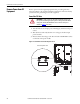
PowerFlex 750-Series Power Option Cabinets 1. Remove closing plates from the right side of the PowerFlex 755 drive cabinet. Typical Right Side Cabinet Mounting Reserve the closing plates and screws. They will be needed to close the exposed side of the power option cabinet. ➊ ➊ ➋ ➌ ➋ ➊ No. ➊ ➋ ➌ ➊ IP20, NEMA/UL Type 1 enclosure shown. Cabinet door and internal components omitted for clarity. Description Top and bottom wireway closing plates Top and bottom PE bus-bar access closing plates.
PowerFlex 750-Series Power Option Cabinets 7. Install the closing plates removed in Step 1 from the drive cabinet on the right side of power option cabinet. IMPORTANT 30 IP54 rated cabinet closing plates are gasketed.
PowerFlex 750-Series Power Option Cabinets Figure 4 - 600 mm (23.6 in.) Cabinet Right Alignment and Hole Pattern T40 6.2 N•m (55.0 lb•in) Figure 5 - 800 mm (31.5 in.) Cabinet Right Alignment and Hole Pattern T40 6.2 N•m (55.
PowerFlex 750-Series Power Option Cabinets 1. Remove closing plates from the left side of the PowerFlex 755 drive cabinet. Typical Left Side Cabinet Mounting Reserve the closing plates and screws. They will be needed to close the exposed side of the power option cabinet. ➊ ➊ ➋ ➌ ➋ IP20, NEMA/UL Type 1 enclosure shown. Cabinet door and internal components omitted for clarity. ➊ ➊ No. ➊ ➋ ➌ Description Top and bottom wireway closing plates. Top and bottom PE bus-bar access closing plates.
PowerFlex 750-Series Power Option Cabinets 7. Install the closing plates removed in Step 1 from the drive cabinet on the left side of power option cabinet.
PowerFlex 750-Series Power Option Cabinets Figure 6 - 600 mm (23.6 in.) Cabinet Left Alignment and Hole Pattern T40 6.2 N•m (55.0 lb•in) Figure 7 - 800 mm (31.5 in.) Cabinet Left Alignment and Hole Pattern T40 6.2 N•m (55.
PowerFlex 750-Series Power Option Cabinets Notes: Rockwell Automation Publication 750-IN030B-EN-P - October 2014 35
Rockwell Automation Support Rockwell Automation provides technical information on the Web to assist you in using its products. At http://www.rockwellautomation.com/support you can find technical and application notes, sample code, and links to software service packs. You can also visit our Support Center at https://rockwellautomation.custhelp.com/ for software updates, support chats and forums, technical information, FAQs, and to sign up for product notification updates.