
User Manual


3-2 Programming and Parameters
PowerFlex 700L Active Converter Power Module User Manual
Publication PFLEX-UM002D-EN-P
How Parameters are
Organized
The LCD HIM displays parameters in a File-Group-Parameter or Numbered
List view order. To switch display mode, access the Main Menu, press ALT,
then Sel while cursor is on the parameter selection.
File-Group-Parameter Order
This simplifies programming by grouping parameters that are used for
similar functions. The parameters are organized into 7 files. Each file is
divided into groups, and each group contains a set of parameters related to a
specific purpose.
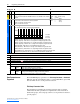
File
Group
No. Parameter Name & Description Values
LIMIT…
Current
100 [Active I Lmt]]
Sets the current limit used when the IGBT overload is less than 90% of the IT fault
threshold.
Default:
Min/Max:
Units:
Rated Amps*1.5
Rated ÷ 4/Rated*1.5 Amps
0.1 Amps
UTILITY
Drive…
197 [Reset to Defaults]
Resets all values in the Converter to the factory defaults.
“Ready” = A new value may be entered.
“Factory” = Parameters are reset.
Default:
Options:
0
0
1
“Ready”
“Ready”
“Factory”
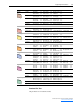
Fault Queue
238 [Fault Config]
A set of bits that select which conditions may generate faults.
• Bit 0 (Ac Low Volt) – When this bit is set, Low AC Line Voltage will generate a fault.
• Bit 1 (Ac High Volt) – When this bit is set, High AC Line Voltage will generate a fault.
• Bit 2 (Ac Low Freq) – When this bit is set, Low AC Line Frequency will generate a fault.
• Bit 3 (Ac High Freq) – When this bit is set, High AC Line Frequency will generate a fault.
• Bit 4 (High dFdt) – When this bit is set, High dF/dt will generate a fault.
• Bit 5 (I Imbalance) – When this bit is set, high current imbalance will generate a fault.
• Bit 6 (V Imbalance) – When this bit is set, high voltage imbalance will generate a fault.
• Bit 7 (PWM SyncLost) - When this bit is set, loss of PWM synchronization will generate a fault.
• Bit 8 (Inverter Flt) - When this bit is set, the Converter will fault when the Inverter faults.
Bit
Definition
Inverter Flt
PWM SyncLost
V Imbalance
I Imbalance
High dFdt
Ac High Freq
Ac Low Freq
Ac High Volt
Ac Low Volt
Default xxxxxxx101101100
Bit 1514131211109876543210
0 = Disabled
1 = Enabled
x = Reserved
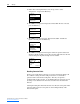
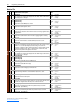
➊➌➋
➎
➍
No. Description
➊
File – Lists the major parameter file category.
➋
Group – Lists the parameter group within a file.
➌
No. – Parameter number. = Parameter value cannot be changed until Converter is stopped.
➍
Parameter Name & Description – Parameter name as it appears on an LCD HIM, with a brief description of the parameters function.
➎
Values – Defines the various operating characteristics of the parameter. Three types exist.
ENUM Default:
Options:
Lists the value assigned at the factory. “Read Only” = no default.
Displays the programming selections available.
Bit Bit: Lists the bit place holder and definition for each bit.
Numeric Default:
Min/Max:
Units:
Lists the value assigned at the factory. “Read Only” = no default.
The range (lowest and highest setting) possible for the parameter.
Unit of measure and resolution as shown on the LCD HIM.