
Specifications
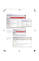

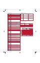

PARAMETERS
No. Name Description
01 Mode Displays the mode selected by the J2 jumper (Single or Multi-Drive).
02 Reserved
03 Reserved
04 P-DP Addr Actual Displays the node address actually used by the adapter.
05 P-DP Rate Actual Displays the data rate actually used by the adapter.
06 Reserved
07 Reserved
08 Reset Module Used to reset the adapter or set defaults.
09 Comm Flt Action Sets the action that the adapter will take if it detects that
communications have been disrupted.
10 Idle Flt Action Sets the action that the adapter will take if it detects that the scanner is idle.
11 DSI I/O Config Selects the I/O that is transferred through the adapter.
12 DSI I/O Active Displays the I/O that the adapter is actively transmitting.
13 Flt Cfg Logic Sets the data that is sent to the drive if any of the following is true:
14 Flt Cfg Ref • Parameter 09 - [Comm Flt Action] is set to Send Flt Cfg and
communications are disrupted.
• Parameter 10 - [Idle Fault Action] is set to Send Flt Cfg and the
scanner is put into Program mode.
15 Reserved
16 Reserved
17 Drv 0 Addr Sets the corresponding node addresses of the daisy-chained drives
18 Drv 1 Addr
used in Multi-Drive mode.
19 Drv 2 Addr
20 Drv 3 Addr
21 Drv 4 Addr
22 Reserved
23 Reserved
24 P-DP State Displays the state of the PROFIBUS controller.
SPECIFICATIONS
Communications Network Protocol PROFIBUS DP
Data Rates 9600 – 12 Mbps (autobauds)
Drive Protocol DSI
Electrical Consumption Drive (DSI) 370 mA at 5 VDC
Network N/A
Regulatory UL UL508C
Compliance cUL CAN/CSA C22.2 No. 14-M91
CE EN50178 and EN61800-3
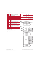
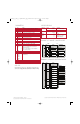
EXAMPLE I/O IMAGE - SINGLE MODE
Controller
Scanner Adapter PowerFlex 40 Drive
Profibus
DSI
Output
Image
(Write)
Input
Image
(Read)
Message
Handler
Message
Buffer
0 Logic Status
1 Feedback
Logic Status
Feedback
Word and I/O
Message
Handler
0 Logic Command
1 Reference
Logic Command
Reference
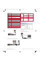
Controller Scanner Adapter
PF 40 Drive 0
Profibus
DSI
Output
Image
(Write)
Input
Image
(Read)
Message
Handler
Message
Buffer
Word and I/O
0 Logic Command
1 Reference
2 Logic Command
3 Reference
4 Logic Command
5 Reference
6 Logic Command
7 Reference
8 Logic Command
9 Reference
0 Logic Status
1 Feedback
2 Logic Status
3 Feedback
4 Logic Status
5 Feedback
6 Logic Status
7 Feedback
8 Logic Status
9 Feedback
PF 4/40 Drive 0-1
PF 4/40 Drive 0-2
PF 4/40 Drive 0-3
PF 4/40 Drive 0-4
PF 40 Drive 0
PF 4/40 Drive 0-1
PF 4/40 Drive 0-2
PF 4/40 Drive 0-3
PF 4/40 Drive 0-4
EXAMPLE I/O IMAGE - MULTI-DRIVE MODE
GSD FILE
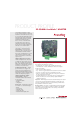
The GSD file is provided on 3.5” disk with the adapter and can be
downloaded at: http://www.ab.com/drives/22-comm/22-comm-p
Publication 22COMM-PP001D-EN-P – July 2006 Copyright ©2006 Rockwell Automation, Inc. All Rights Reserved. Printed in USA.
Supersedes Publication 22COMM-PP001C-EN-P – December 2005
22comm_P_PP_NL_8_23.qxd:Product_app_profile5-18-05.qxd 8/23/06 2:55 PM Page 2