
Technical data


16 Rockwell Automation Publication 22-TD001I-EN-P - June 2013
PowerFlex 4 and 40 AC Drives
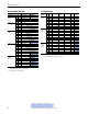
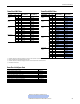
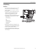
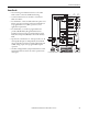
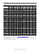
No. Signal Default Description
R1 Relay N.O. Fault Normally open contact for output relay.
R2 Relay Common – Common for output relay.
R3 Relay N.C. Fault Normally closed contact for output relay.
Sink/Source DIP Switch Source (SRC) Inputs can be wired as Sink (SNK) or Source (SRC) via DIP Switch setting.
01 Stop
(1)
(1) Only one analog frequency source may be connected at a time. If more than one reference is connected at the same time, an undetermined frequency reference will result.
Coast The factory installed jumper or a normally closed input must be present for the drive to start.
02 Start/Run FWD Not Active Command comes from the integral keypad by default. To disable reverse operation, see A095 [Reverse Disable].
03 Direction/Run REV Not Active
04 Digital Common – For digital inputs. Electronically isolated with digital inputs from analog I/O.
05 Digital Input 1 Preset Freq Program with A051 [Digital In1 Sel].
06 Digital Input 2 Preset Freq Program with A052 [Digital In2 Sel].
11 +24V DC – Drive supplied power for digital inputs.
Maximum output current is 100 mA.
12 +10V DC – Drive supplied power for 0…10V external potentiometer.
Maximum output current is 15 mA.
13 0…10V In
(1)
Not Active For external 0…10V input supply
(input impedance = 100k ohm) or potentiometer wiper.
14 Analog Common – For 0…10V In or 4…20 mA In. Electronically isolated with analog inputs from digital I/O.
15 4…20 mA In
(1)
Not Active For external 4…20 mA input supply
(input impedance = 250 ohm).
16 RS485 (DSI) Shield – Terminal should be connected to safety ground - PE when using the RS485 (DSI) communications port.
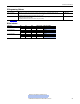
30V DC 125V AC 240V AC
Resistive 3.0 A 3.0 A 3.0 A
Inductive 0.5 A 0.5 A 0.5 A