Installation Instructions PowerFlex 40 Configured AC Drives Catalog Numbers 23B
Important User Information Read this document and the documents listed in the additional resources section about installation, configuration, and operation of this equipment before you install, configure, operate, or maintain this product. Users are required to familiarize themselves with installation and wiring instructions in addition to requirements of all applicable codes, laws, and standards.
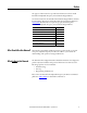
Table of Contents Preface Who Should Use this Manual? . . . . . . . . . . . . . . . . . . . . . . . . . . . . . . . . . . . . . . 5 What Is Not in this Manual. . . . . . . . . . . . . . . . . . . . . . . . . . . . . . . . . . . . . . . . . 5 Additional Resources . . . . . . . . . . . . . . . . . . . . . . . . . . . . . . . . . . . . . . . . . . . . . . . 6 Manual Conventions . . . . . . . . . . . . . . . . . . . . . . . . . . . . . . . . . . . . . . . . . . . . . . . 6 General Precautions . . . . . . . . .
Table of Contents Chapter 2 Control Wiring Overview Control Wiring Overview. . . . . . . . . . . . . . . . . . . . . . . . . . . . . . . . . . . . . . . . . 27 Schematic Drawings . . . . . . . . . . . . . . . . . . . . . . . . . . . . . . . . . . . . . . . . . . . . . . 28 Chapter 3 Mechanical Installation Mounting Considerations. . . . . . . . . . . . . . . . . . . . . . . . . . . . . . . . . . . . . . . . . Environment . . . . . . . . . . . . . . . . . . . . . . . . . . . . . . . . . . . . . . . . . .
Preface The purpose of this manual is to provide basic information needed to install PowerFlex 40 Adjustable Frequency AC Standard Configured Drives. User documentation for the PowerFlex 40 Standard Configured Drives includes these Installation Instructions and the PowerFlex 40 User Manual, publication 22B-UM001. Both manuals are required to properly install and operate PowerFlex 40 Adjustable Frequency AC Standard Configured Drives.
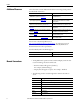
Preface Additional Resources These documents contain additional information concerning related products from Rockwell Automation. Resource Description Wiring and Grounding Guidelines for Pulse Width Modulated (PWM) AC Drives, publication DRIVES-IN001 Provides basic information needed to properly wire and ground PWM AC drives.
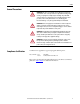
Preface General Precautions ATTENTION: This drive contains ESD (Electrostatic Discharge) sensitive parts and assemblies. Static control precautions are required when installing, testing, servicing or repairing this assembly. Component damage may result if ESD control procedures are not followed. If you are not familiar with static control procedures, reference A-B publication 8000-4.5.2, “Guarding Against Electrostatic Damage” or any other applicable ESD protection handbook.
Preface Catalog Number Explanation The PowerFlex 40 Adjustable Frequency AC Standard Configured Drives catalog numbering scheme is shown below.
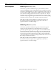
Chapter 1 PowerFlex 40 Standard Configured Drive Standard Features and Options For information on … See page … Standard Features 9 Enclosure Options 10 Communication Options 11 Power Disconnect Options 12 Operator Device Options 17 Quick Disconnects 23 I/O Options 24 This chapter describes the standard features and operation for PowerFlex 40 Standard Configured Drives and associated options. Standard Features This package integrates the Standard PowerFlex 40 drive.
Chapter 1 PowerFlex 40 Standard Configured Drive Standard Features and Options Enclosure Options NEMA/UL Type 4 (Position 9, Code D) The enclosure provided is a NEMA/UL Type 4, painted mild steel, which supports both NEMA/UL Type 4 and NEMA/UL Type 12 applications. Type 4 enclosures are intended for indoor or outdoor use primarily to provide a degree of protection against windblown dust and rain, splashing water, and hose directed water, and to be undamaged by the formation of ice on the enclosure.
PowerFlex 40 Standard Configured Drive Standard Features and Options Communication Options Chapter 1 DeviceNet (Position 12, Code D) The DeviceNet option is drive mounted and consists of the DeviceNet communication adaptor (22-COMM-D) and adaptor cover (22B-CCB for frame B drives or 22B-CCC for frame C drives). When DeviceNet is present, no other communication option is available other than the HIM. When used as a slave, the HIM will have limited functionality.
Chapter 1 PowerFlex 40 Standard Configured Drive Standard Features and Options Power Disconnect Options Drive Motor Circuit Protector (Position 16+, Code P3) The Drive Motor Circuit Protector option is factory installed and provides a manual means of disconnecting input power to the drive. The Allen-Bradley bulletin 140M switch is designed to meet short circuit requirements for branch circuit protection. The rotary style handle is padlockable in On or Off position.
PowerFlex 40 Standard Configured Drive Standard Features and Options Chapter 1 Drive Input Fused Disconnect Switch (Position 16+, Code P6) The Drive Input Fused Disconnect Switch option is factory installed and provides a manual means of disconnecting input power to the drive. The AllenBradley Bulletin 194R switch is designed to meet disconnect switch requirements for branch circuit protection. The rotary style handle is padlockable in On or Off position.
Chapter 1 PowerFlex 40 Standard Configured Drive Standard Features and Options Main Fuses (F1-F3) ATTENTION: Most codes require that upstream branch circuit protection be provided to protect input power wiring. Install the fuses recommended in Table 2. Do not exceed the fuse ratings. Failure to observe this precaution could result in damage to, or destruction of, the equipment. Input line branch circuit protection fuses must be used to protect the input power lines.
PowerFlex 40 Standard Configured Drive Standard Features and Options Chapter 1 Input Power Wiring Refer to the PowerFlex 40 User Manual for additional detailed information about input power wiring recommendations and selection. ATTENTION: Protect the contents of the options cabinet from metal chips and other debris while drilling the conduit openings. Failure to observe this precaution could result in damage to, or destruction of, the equipment.
Chapter 1 PowerFlex 40 Standard Configured Drive Standard Features and Options Output Power Wiring Refer to the PowerFlex 40 User Manual for additional detailed information about output power wiring recommendations and selection. ATTENTION: Unused wires in conduit must be grounded at both ends to avoid a possible shock hazard caused by induced voltages.
PowerFlex 40 Standard Configured Drive Standard Features and Options Operator Device Options Chapter 1 Hand/Off/Auto Selector Switch (Position 16+, Code S1) This 800F door mounted operator device is factory installed and provides a Hand/Off/Auto selector switch. The Hand/Off/Auto selector switch will start the drive in Hand mode and stop the drive in Off mode. In Auto mode the drive will be stopped and started from remote contact closures.
Chapter 1 PowerFlex 40 Standard Configured Drive Standard Features and Options Auto/Manual Selector Switch (Position 16+, Code S4) This 800F door mounted operator device is factory installed and provides an Auto/Manual selector switch. The Auto/Manual selector switch determines the source of the actual drive speed reference. Using 2-wire control in Auto mode, speed source is parameter A071 [Preset Freq 1]. In Manual mode, the speed source is parameter A072 [Preset Freq 2].
PowerFlex 40 Standard Configured Drive Standard Features and Options Chapter 1 Start and Stop Push Buttons (Position 16+, Code S7) This option provides factory installed 800F Start and Stop push buttons. In all cases, the Stop input to the drive must be present before the drive will start. Using 3-wire control, speed source is parameter A070 [Preset Freq 0]. The Stop push button may also be used as a fault reset.
Chapter 1 PowerFlex 40 Standard Configured Drive Standard Features and Options Local Speed Potentiometer (Code S18) This option provides a factory installed 800F door mounted one turn potentiometer for speed control. The device provides the speed source when no digital inputs are active. When this option is provided, it becomes the speed source for the Hand mode of the Hand/Off/Auto selector switch (Option S1) and the Manual mode of the Auto/Manual selector switch (Option S4).
PowerFlex 40 Standard Configured Drive Standard Features and Options Chapter 1 Local/Off/Remote Selector Switch With One Normally Open Interposing Relay (Code S21) This 800F door mounted operator device and interposing relay option is factory installed and provides a Local/Off/Remote selector switch. The Local/Off/Remote selector switch will start the drive in Local mode and stop it in Off mode.
Chapter 1 PowerFlex 40 Standard Configured Drive Standard Features and Options Spring Return Hand-Off-Auto Selector Switch (Code S22) This 800F door mounted operator device is factory installed and provides a Hand/Off/Auto selector switch. The Hand position is equipped with a spring return. The Hand/Off/Auto selector switch will start the drive while held in Hand mode and stop the drive in Off mode. The selector switch has a spring return disallowing the operator to remain in Hand.
PowerFlex 40 Standard Configured Drive Standard Features and Options Chapter 1 Clear Fault Push Button (Code S23) This option provides a factory installed 800F Clear Fault push button. Component Specifications Bulletin 800F Devices Clear Fault Push Button: Legend Plate Wiring Schematic IEC style, Internationally rated Meet IP65/IP66 and NEMA/UL Type 4/4X/13 UL Listed, CSA Certified 10 amp contacts Screw terminals, 0.3…3.5 mm2 (22…12 AWG) maximum Flush head, Black, 1 N.O.
Chapter 1 PowerFlex 40 Standard Configured Drive Standard Features and Options I/O Options DeviceNet I/O (4 In/2 Out) w/Spring Return HOA and Power Disconnect Aux. Contact (Position 16+, Code R3) This option provides a factory installed 800F door mounted operator device, a 100-DNY42R and a power disconnect auxiliary contact mounted internal to the cabinet. The Hand/Off/Auto selector switch will start the drive while held in the Hand mode and stop it in the Off mode.
PowerFlex 40 Standard Configured Drive Standard Features and Options Chapter 1 DeviceNet Point I/O w/IB4 (4 Inputs) (Position 16+, Code R4) This option provides a factory installed 1734-ADNX Point I/O Scanner in combination with a 1734-IB4 (4 input) four point, 24V DC sink input. The drive DeviceNet is prewired to the subnet connector of the 1734-ADNX. The customer is required to make the DeviceNet connection directly to the 1734-ADNX network connector.
Chapter 1 PowerFlex 40 Standard Configured Drive Standard Features and Options DeviceNet I/O (4 In/ 2 Out) w/Spring Return HOA, Power Disconnect Aux. Contact, and 4 I/O Quick Disconnects (Position 16+, Code R5) This option provides a factory installed 800F door mounted operator device, a 100-DNY42R mounted internal to the cabinet, a power disconnect auxiliary contact, four I/O quick disconnects, and a 24V DC male receptacle.
Chapter 2 Control Wiring Overview For information on … See page … Control Wiring Overview 27 Schematic Drawings 28 This chapter describes the control and signal wiring connection options. Refer to the PowerFlex 40 User Manual for additional detailed information about control and signal wiring.
Chapter 2 Control Wiring Overview Schematic Drawings Figure 1 - Power Distribution Option A B C D E F G H 1 1 2 2 3 3 4 4 5 L1 6 DISCONNECTING MEANS AND SHORT CIRCUIT PROTECTION PROVIDED BY OTHERS WHEN P3, P3T, P6 OR P6T OPTIONS ARE NOT ORDERED L2 480 VOLTS 3PH, 50/60HZ AC LINES 7 L3 5 1051 POWER DISCONNECTING OPTION 1061 9 CHASSIS 10 L1 F1 T1 L2 F2 T2 L3 F3 T3 9 10 DEVICENET CONNECTOR OPTIONS 13 R S POWER TERMINAL BLOCK COMM.
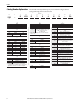
Control Wiring Overview Chapter 2 Figure 2 - Drive Ratings A B C D E F G H 1 1 2 2 3 3 4 4 5 5 TABLE 2 6 6 7 7 THREE PHASE 8 9 DRIVE RATINGS CATALOG NO. 10 11 12 13 14 FRAME 8 P6/P6T OPTIONS P3/P3T OPTIONS P3 OPTION 9 AMP VOLT CATALOG NO. CATALOG NO. KIT NO. 10 FUSE RATINGS (P6 OPTION) HP VOLTAGE FLA TYPE 22B-D1P4F104 22B-D2P3F104 22B-D4P0F104 22B-D6P0F104 22B-D010F104 B B B B B .5 1 2 3 5 342-528 342-528 342-528 342-528 342-528 1.4 2.3 4.0 6.0 10.
Chapter 2 Control Wiring Overview Figure 3 - Control Logic Options 4, C, D, E & P A B C D E F G H 1 1 I/O TERMINAL BLOCK 2 2021 SNK 1 STOP 3 4 6 FAN RED 7 BLACK 3 X SRC 2 START/RUN FWD P036 = 5 COMM PORT P038 = 5 COMM PORT 3 DIR/RUN REV 4 DIGITAL COMMON 5 DIGITAL IN1 6 DIGITAL IN2 7 DIGITAL IN3 8 DIGITAL IN4 9 OPTO COMMON 5 2 4 5 6 7 8 8 9 10 9 10 11 11 12 13 12 13 14 14 15 15 2021 11 +24V DC 16 17 16 17 12 +10V DC 18 18 13 0-10V IN 19 20 19 20 14 ANA
Control Wiring Overview Chapter 2 Figure 4 - Control Logic Option S1 1 AUTO I/O TERMINAL BLOCK 2022 4 OOX 3 4 6 FAN RED 7 BLACK 3 X SRC 2 START/RUN FWD P036 = 2 "2-WIRE" P038 = 4 "PRESET FREQ.
Chapter 2 Control Wiring Overview Figure 5 - Control Logic Option S1 & S8 1 AUTO I/O TERMINAL BLOCK 2022 4 OOX 3 4 * 5 6 8 9 10 OOX 3 XOO 3 11 1 2 OX 4 3 FAN RED 7 XO 2052 BLACK START/RUN FWD P036 = 2 "2-WIRE" P038 = 4 "PRESET FREQ.
Control Wiring Overview Chapter 2 Figure 6 - Control Logic Option S4 A B C D E F G H 1 1 I/O TERMINAL BLOCK 2 2021 SNK 1 STOP 3 2-WIRE DEVICE 4 * 5 6 FAN RED 7 AUTO 8 9 10 11 BLACK 2 3 X SRC 2 START/RUN FWD P036 = 1 "3-WIRE" P038 = 4 "PRESET FREQ.
Chapter 2 Control Wiring Overview Figure 7 - Control Logic Option S4 & S7 A B C D E F G H 1 1 2 I/O TERMINAL BLOCK STOP 2021 1 3 3 2022 2041 4 PB2 5 6 FAN RED 7 AUTO 8 9 10 11 BLACK 2 SNK 1 STOP PB3 START 4 2 3 X SRC 2 START/RUN FWD P036 = 1 "3-WIRE" P038 = 4 "PRESET FREQ.
Control Wiring Overview Chapter 2 Figure 8 - Control Logic Option S4 with S8 A B C D E F G H 1 1 I/O TERMINAL BLOCK 2 2021 3 FORWARD 4 XO 1 2 OX 3 4 2 START/RUN FWD P036 = 2 "2-WIRE" P038 = 4 "PRESET FREQ.
Chapter 2 Control Wiring Overview Figure 9 - Control Logic Option S7 A B C D E F G H 1 1 2 I/O TERMINAL BLOCK STOP 2021 1 3 3 2022 2041 4 PB2 5 6 FAN RED 7 BLACK 2 SNK 1 STOP PB3 START 4 2 3 X SRC 2 START/RUN FWD P036 = 1 "3-WIRE" P038 = 4 "PRESET FREQ.
Control Wiring Overview Chapter 2 Figure 10 - Control Logic Option S7 and S8 A B C D E F G H 1 1 2 I/O TERMINAL BLOCK STOP 2021 1 3 3 FORWARD 5 OX 6 4 2041 4 2052 SS3 FAN RED 7 BLACK 2 SNK 1 STOP PB2 REVERSE 3 2022 PB3 START 4 2 3 X SRC 2 START/RUN FWD P036 = 1 "3-WIRE" P038 = 4 "PRESET FREQ.
Chapter 2 Control Wiring Overview Figure 11 - Control Logic Option S8 A B C D E F G H 1 1 I/O TERMINAL BLOCK 2 2021 3 FORWARD 4 XO 1 2 OX 3 4 2 START/RUN FWD P036 = 2 "2-WIRE" P038 = 4 "PRESET FREQ.
Control Wiring Overview Chapter 2 Figure 12 - Control Logic Option S20 A B C D E F G H 1 1 I/O TERMINAL BLOCK 2 2021 3 LOCAL CONTROL RUN FORWARD OFF 2042 3 4 OX SS2 4 5 6 FAN RED 7 OX 9 BLACK 3 X SRC 2 START/RUN FWD P036 = 2 "2-WIRE" P038 = 4 "PRESET FREQ.
Chapter 2 Control Wiring Overview Figure 13 - Control Logic Option S18 A B C D E F G H 1 1 I/O TERMINAL BLOCK 2 2021 3 4 6 FAN RED 7 BLACK 3 X SRC 2 START/RUN FWD P036 = 2 "2-WIRE" P038 = 2 "0-10V INPUT" 3 DIR/RUN REV 4 DIGITAL COMMON 5 DIGITAL IN1 6 DIGITAL IN2 7 DIGITAL IN3 8 DIGITAL IN4 9 OPTO COMMON 5 2 SNK 1 STOP 4 5 6 7 8 8 9 10 9 10 11 11 12 13 12 13 14 14 15 15 2021 11 +24V DC 16 16 17 17 18 SPEED REFERENCE RH1 10K 19 12 +10V DC 2181 18
Control Wiring Overview Chapter 2 Figure 14 - Control Logic Option S21 3 4 OOX 5 3 1 REMOTE I/O TERMINAL BLOCK 2022 4 3 A XOO B 2021 C 2 D OFF LOCAL E F G H 1 CR1 2041 4 6 FAN RED 7 BLACK 3 X SRC 2 START/RUN FWD P036 = 2 "2-WIRE" P038 = 4 "PRESET FREQ.
Chapter 2 Control Wiring Overview Figure 15 - Control Logic Option S22 3 XOO 3 1 AUTO I/O TERMINAL BLOCK 2022 4 OOX 3 4 6 FAN RED 7 BLACK 3 X SRC 2 START/RUN FWD P036 = 2 "2-WIRE" P038 = 4 "PRESET FREQ.
Control Wiring Overview Chapter 2 Figure 16 - Control Logic Option S22 & S8 3 3 1 AUTO I/O TERMINAL BLOCK 2022 4 FORWARD OOX 3 4 * 5 6 8 9 10 OOX 3 XOO 3 11 1 2 OX 4 3 FAN RED 7 XO 2052 BLACK 3 DIR/RUN REV 4 DIGITAL COMMON 5 DIGITAL IN1 A051 = 4 "PRESET FREQ" 6 DIGITAL IN2 A052 = 4 "PRESET FREQ" 7 DIGITAL IN3 8 DIGITAL IN4 9 OPTO COMMON 4 5 6 7 8 2101 4 2 START/RUN FWD P036 = 2 "2-WIRE" P038 = 4 "PRESET FREQ.
Chapter 2 Control Wiring Overview Figure 17 - Control Logic Option S23 A B C D E F G H 1 1 I/O TERMINAL BLOCK 2 2021 3 4 FAN RED 7 BLACK 3 X SRC 4 2 START/RUN FWD P036 = 5 "COMM PORT" P038 = 5 "COMM PORT" 3 DIR/RUN REV 4 DIGITAL COMMON 5 DIGITAL IN1 A051 = 4 "PRESET FREQ" 9 6 DIGITAL IN2 10 7 DIGITAL IN3 8 DIGITAL IN4 A054 = 7 "CLEAR FAULT" 9 OPTO COMMON 5 6 2 SNK 1 STOP 5 6 7 8 8 9 10 11 11 12 12 CLEAR FAULT 2021 13 3 4 2132 PB1 14 15 13 14 15 2021
Control Wiring Overview Chapter 2 Figure 18 - Control Logic Option R3 with P3/P3T or P6/P6T 2021 3 4 XOO XOO 1 1 AUTO 2 1 2 3 4 I/O TERMINAL BLOCK 2022 2042 OOX RED 7 8 OOX BULLETIN 100 DEVICENET SYSTEM ACCESSORY 10 14 OOX 3 4 3 4 2082 COM CAN L SHD CAN H V+ TO 1-19 2131 IN1 2102 START/RUN FWD P036 = 2 "2-WIRE" P038 = 4 "PRESET FREQ.
Chapter 2 Control Wiring Overview Figure 19 - Control Logic Option R4 A B C D E F G H 1 1 2 2 EA4 3 3 1734-ADNX POINT I/O SCANNER 4 5 5 COM CAN L SHD CAN H V+ CUSTOMER DEVICE-NET CONNECTION 6 4 7 7 NETWORK CONNECTOR 5-PIN CONNECTOR 8 6 8 * 9 10 9 COM CAN L SHD CAN H V+ FROM 1-19 11 10 11 SUBNET CONNECTOR 12 13 13 C C 4 5 6 7 V V CUSTOMER SUPPLIED 12/24 VDC 14 12 14 4-PIN RECEPTACLE 15 BROWN 16 WHITE 17 BLUE 4-PIN RECEPTACLE SCHEMATIC DRAWING, POWERFLEX 40
Control Wiring Overview Chapter 2 Figure 20 - Control Logic Option R5 with P3/P3T or P6/P6T 2021 3 XOO 4 XOO AUTO 1 2 1 2 3 4 I/O TERMINAL BLOCK 2022 2042 OOX RED 7 8 OOX BULLETIN 100 DEVICENET SYSTEM ACCESSORY 10 OOX IN0 12 14 2101 V+ 11 TO 1-19 2121 IN1 VCAN L SHD CAN H V+ 2 START/RUN FWD P036 = 2 "2-WIRE" P038 = 4 "PRESET FREQ.
Chapter 2 Control Wiring Overview Figure 21 - Interconnect Wire & Parts List A B C D E F G H REPLACEMENT COMPONENTS LIST 1 SYM. 2 3 4 5 6 7 8 9 10 11 1 A-B PART NO. N/A N/A N/A N/A N/A N/A N/A N/A N/A N/A N/A N/A N/A N/A N/A N/A N/A DESCRIPTION MANUFACTURER/PART NO. EA1 F1-3 DS1 MCP1 EA1 EA1 EA1 EA1 EA1 SS1 SS2 SS3 PB1 PB2 PB3 CR1 FAN DRIVE UNIT FUSES DISCONNECT MTR CIRCUIT PROT.
Chapter 3 Mechanical Installation For information on … See page … Mounting Considerations 49 Dimensions 50 Layout Drawings 52 This chapter provides information on mounting a PowerFlex 40 Standard Configured Drive. ATTENTION: The following information is merely a guide for proper installation. The Allen-Bradley Company cannot assume responsibility for the compliance or the noncompliance to any code, national, local or otherwise for the proper installation of this drive or associated equipment.
Chapter 3 Mechanical Installation Figure 22 - Minimum Mounting Clearances Dimensions are in millimeters and (inches). 152.4 (6.00) Drive or other device 152.4 (6.00) 152.4 (6.00) 152.4 (6.00) Dimensions Figure 23 - Frame B Dimensions Dimensions are in millimeters and (inches). 405.9 (15.98) 9.4 (0.37) 393.2 (15.48) 355.6 (14.00) 336.6 (13.25) 298.5 (11.75) 177.8 (7.00) 69.3 (2.73) 355.1 (13.98) 342.4 (13.48) 304.8 (12.00) 285.8 (11.25) 6.35 (0.25) Optional mounting bracket orientation.
Mechanical Installation Chapter 3 Figure 24 - Frame C Dimensions Dimensions are in millimeters and (inches). P3 Option 383.3 (15.09) Frame C 16.0 (0.63) 457.2 (18.00) 425.2 (16.74) P6 Option 375.2 (14.77) 177.8 (7.00) 146.1 (5.75) 460.8 (18.14) 427.2 (16.82) 406.4 (16.00) Detail 19.1 (0.75) 9.7 (0.38) 19.1 (0.75) Rockwell Automation Publication 23B-IN001K-EN-P - September 2013 12.7 (0.
Chapter 3 Mechanical Installation Layout Drawings 52 Figure 25 - PowerFlex 40 Frame B Layout Drawing Rockwell Automation Publication 23B-IN001K-EN-P - September 2013
Mechanical Installation Chapter 3 Figure 26 - PowerFlex 40 Frame C Layout Drawing Rockwell Automation Publication 23B-IN001K-EN-P - September 2013 53
Chapter 3 Mechanical Installation Figure 27 - PowerFlex 40 General Option Layout Drawing 54 Rockwell Automation Publication 23B-IN001K-EN-P - September 2013
Appendix A Specifications The following tables provide specifications for the PowerFlex 40 configured AC drives. Specifications Tables Input/Output Ratings Approvals Table 6 - Standard Configured Drive Products Output Frequency: Efficiency: TED 966X LIS UL ® IN Fuses and Power Disconnecting Means 0…400 Hz (Programmable) 97.5% (Typical) TED 966X LIS UL508C C D C ONT EQ UL ® IN CSA C 22.2 No.
Appendix A Specifications Dynamic Braking Internal brake IGBT included with all ratings Environment Altitude: Storage Temperature: Atmosphere: Relative Humidity: Shock (operating): Vibration (operating): Control 56 1000 m (3300 ft) max. without derating –40 to 85 degrees C (–40 to 185 degrees F) Important: Drive must not be installed in an area where the ambient atmosphere contains volatile or corrosive gas, vapors or dust.
Appendix B Replacement Parts The following tables provide spare part information for the PowerFlex 40 configured AC drive. Spare Parts Lists Table 8 - Components Description Motor Circuit Protector Option P3 or P3T Replacement Kit (1) Designation MCP1 MCP1 Voltage 480V AC 480V AC Option P3 HP Part Number Manufacturer 0.5 140M-C2E-B40(2) Allen-Bradley 1.0 140M-C2E-B63(2) Allen-Bradley 2.0 140M-D8E-C10(2) Allen-Bradley 3.0 140M-D8E-C16(2) Allen-Bradley 5.
Appendix B Replacement Parts Description Designation Voltage HP Part Number Manufacturer Operator Shaft Option DS1 P6 or P6T 480V AC 0.5…15 194R-S1 Allen-Bradley Main Fuses Option P6 or P6T 480V AC 0.5 LPJ-3SP Bussman AJT-3 Ferraz-Shawmut 1.0 LPJ-6SP Bussman 2.
Replacement Parts Appendix B Table 9 - Communication Options Description ControlNet DeviceNet EtherNet PROFIBUS Adaptor Frame B Frame C Designation EA1 EA1 EA1 EA1 Voltage All All All All HP All All All All Part Number 22-COMM-C 22-COMM-D 22-COMM-E 22-COMM-P Manufacturer Allen-Bradley Allen-Bradley Allen-Bradley Allen-Bradley EA1 EA1 All All 0.5…5.0 7.
Appendix B Replacement Parts Option Description Designation Voltage HP Part Number Manufacturer Option S21 Selector Switch Anti-Rotation Switch Mounting Latch Contact Block - 2 N.O.
Rockwell Automation Support Rockwell Automation provides technical information on the Web to assist you in using its products. At http://www.rockwellautomation.com/support you can find technical and application notes, sample code, and links to software service packs. You can also visit our Support Center at https://rockwellautomation.custhelp.com/ for software updates, support chats and forums, technical information, FAQs, and to sign up for product notification updates.