
Quick Start - FRN 1.xx - 3.xx Instruction Manual


English-7
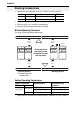
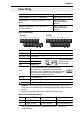
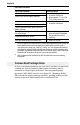
Power Terminal Block
Power Terminal Block Specifications
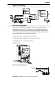
Power Wiring
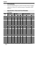
Power Wire Rating Recommended Copper Wire
Unshielded 600V, 75°C (167°F) THHN/THWN 15 Mils insulated, dry location
Shielded 600V, 75°C or 90°C (167°F or 194°F) RHH/
RHW-2
Anixter OLF-7xxxxx,
Belden 29501-29507 or
equivalent
Shielded Tray rated 600V, 75°C or 90°C (167°F or
194°F) RHH/RHW-2
Anixter 7V-7xxxx-3G
Shawflex 2ACD/3ACD or
equivalent
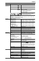
Terminal
(1)
Description
R/L1, S/L2 1-Phase Input
(2)
R/L1, S/L2, T/L3 3-Phase Input
U/T1 To Motor U/T1
=
Switch any two motor
leads to change
forward direction.
V/T2 To Motor V/T2
W/T3 To Motor W/T3
P2, P1
DC Bus Inductor Connection (C Frame drives only.)
The C Frame drive is shipped with a jumper between
Terminals P2 and P1. Remove this jumper only when a DC
Bus Inductor will be connected. Drive will not power up
without a jumper or inductor connected.
DC+, DC- DC Bus Connection
BR+, BR- Dynamic Brake Resistor Connection
Safety Ground - PE
(1)
Important: Terminal screws may become loose during shipment. Ensure that all
terminal screws are tightened to the recommended torque before applying power to
the drive.
(2)
Single-phase operation requires a 65% derate of drive rated current.
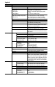
Frame Maximum Wire Size
(1)
Minimum Wire Size
(1)
Torque
B 5.3 mm
2
(10 AWG) 1.3 mm
2
(16 AWG) 1.7-2.2 N-m (16-19 lb.-in.)
C 8.4 mm
2
(8 AWG) 1.3 mm
2
(16 AWG) 2.9-3.7 N-m (26-33 lb.-in.)
(1)
Maximum/minimum sizes that the terminal block will accept - these are not
recommendations.
V/T2T/L3S/L2R/L1 U/T1 W/T3
BR+ BR-DC- DC+
V/T2T/L3S/L2R/L1 U/T1 W/T3 P2 P1
BR+ BR-DC- DC+
B Frame C Frame