
Quick Start FRN 2.xx Instruction Manual

5011656403-4M03
FRN 2.xx
クイックスタート
FRN 2.xx
Quick Start
25 mm (1.0 in.)
120 mm (4.7 in.)
120 mm (4.7 in.)
C
losest object that may obstruct air flow
t
hrough the drive heat sink and chassis
C
losest object that may obstruct air flow
t
hrough the drive heat sink and chassis
120 mm (4.7 in.)
120 mm (4.7 in.)
See Step 1
Airflow
Airflow
T/L3S/L2R/L1
W/T3V/T2U/T1
P2**
P1**
DC-BR-**
BR+**
DC+
Required Branch Circuit Disconnect
01
02
03
04
05
06
11
12
13
14
15
16
Stop
(1)
Start/Run FWD
(2)
Direction/Run REV
Digital Common
Digital Input 1
Digital Input 2
R1
R2
R3
Relay N.O.
Relay Common
Relay N.C.
+24V DC
+10V DC
0-10V In
Analog Common
4-20mA In
RS485 Shield
+24V
+10V
SRCSNK
Typical
SNK Wiring
Typical
SRC Wiring
j
i
k*
a
c
b
d
e
g
h
f
Frame
フレーム
120V AC
1-Phase
120V AC
単相
240V AC
1-Phase
240V AC
単相
240V AC
3-Phase
240V AC
3相
480V AC
3-Phase
480V AC
3相
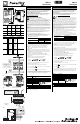
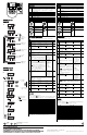
A 0.2 (0.25)
0.4 (0.5)
0.2 (0.25)
0.4 (0.5)
0.75 (1.0)
0.2 (0.25)
0.4 (0.5)
0.75 (1.0)
1.5 (2.0)
0.4 (0.5)
0.75 (1.0)
1.5 (2.0)
B 0.75 (1.0)
1.1 (1.5)
1.5 (2.0)
2.2 (3.0)
2.2 (3.0)
3.7 (5.0)
2.2 (3.0)
3.7 (5.0)
C — — 5.5 (7.5)
7.5 (10.0)
5.5 (7.5)
7.5 (10.0)
11.0 (15.0)
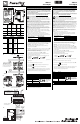
Frame
フレーム
Dimensions
寸法
Shipping Weight
出荷重量
Aa
b
c
d
e
f
72.0 (2.83)
59.0 (2.32)
174.0 (6.85)
151.6 (5.97)
5.4 (0.21)
5.4 (0.21)
g
h
i
j
k
5.2 (0.20)
—
136.0 (5.35)
90.9 (3.58)
81.3 (3.20)
1.6 (3.5)
Ba
b
c
d
e
f
100 (3.94)
89.0 (3.50)
174.0 (6.85)
163.5 (6.44)
5.4 (0.21)
5.4 (0.21)
g
h
i
j
k
5.2 (0.20)
0.5 (0.02)
136.0 (5.35)
90.9 (3.58)
81.3 (3.20)
2.1 (4.6)
Ca
b
c
d
e
f
130.0 (5.12)
116.0 (4.57)
260.0 (10.24)
247.5 (9.74)
5.5 (0.22)
5.5 (0.22)
g
h
i
j
k
6.0 (0.24)
1.0 (0.04)
180.0 (7.09)
128.7 (5.07)
—
4.8 (10.6)
➀
➁
∅
∅
∅
∅
∅
∅
➂
➄
➅
➆
➃
Typic al
SRC Wiring
標準的な SRC
配線
Typ ical
SNK Wiring
標準的な SNK
配線
See Step 1
ス テ ッ プ 1 を 参照 し て く だ さ い。
Closest object that may obstruct air flow
through the drive heat sink and chassis
ドライブのヒートシンクとシャーシ
の通気を妨げる恐れのあ る最も近 く
の物体
Airflow
通気
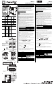
76.2 mm (3.0 in.)
76.2 mm (3.0 in.)
76.2 mm (3.0 in.)
76.2 mm (3.0 in.)
25 mm (1.0 in.)
Required Branch Circuit Disconnect
必要な分岐回路切断
Branch Circuit Protective Device
分岐回路保護デ バ イ ス
Ground Terminal/Protective Earth
グ ラ ウ ン ド 端子 / 保護接地
Motor
モータ
** Frame C only
** フ レ ー ム C の み
English
This Quick Start will guide you through basic installation, wiring and basic parameter setup of
the PowerFlex 4M Adjustable Frequency AC Drive. After completing these tasks, you will be
able to start the motor, check direction of rotation and control speed using the integral keypad
and potentiometer. The information provided does not replace the User Manual and is
intended for qualified drive service personnel only.
This document does not provide instructions for grounding, shields, control I/O, ESD or CE
Conformity. Refer to the PowerFlex 4M User Manual, Publication 22F-UM001… at
www.rockwellautomation.com/literature
.
General Precautions
ATTENTION: You must understand shock hazards, safety practices, electrical codes and
associated machinery to plan or implement the installation, start-up and maintenance of this
drive. Failure to comply may result in personal injury and/or equipment damage.
ATTENTION: The drive contains high voltage capacitors which take time to discharge after
removal of mains supply. Before working on drive, ensure isolation of mains supply from line
inputs [R, S, T (L1, L2, L3)]. Wait three minutes for capacitors to discharge to safe voltage levels.
Failure to do so may result in personal injury or death. Darkened display LEDs is not an
indication that capacitors have discharged to safe voltage levels.
ATTENTION: Equipment damage and/or personal injury may result if parameter A451 [Auto
Rstrt Tries] or A433 [Start At PowerUp] is used in an inappropriate application. Do not use this
function without considering applicable local, national and international codes, standards,
regulations or industry guidelines.
See Tables and . Ratings are in kW and (HP). Dimensions are in millimeters and
(inches). Weights are in kilograms and (pounds). Decimal periods are used in this document.
*DIN rail mounting is applicable to Frame A and B only.
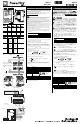
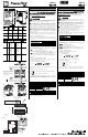
1. Installation must comply with minimum clearances and ambient temperature. Mount
upright on a flat vertical surface with screws or a DIN rail. See Figure and the
following table.
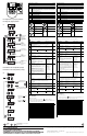
2. The MOV to ground jumper must be removed if the drive is installed on an ungrounded or
resistive grounded distribution system. (Figure )
Important: Tighten screw after jumper removal.
3. Open the finger guards to access the power terminal blocks. (Figure )
Important: Connecting remote devices to the control terminals (Figure ) requires
information in the User Manual. Terminal functions must be configured with related
parameters. Proceed to Step 4 if you want to start the motor using the integral keypad.
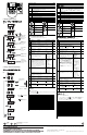
4. Connect the power wires. (Figure and Table )
5. Connect the load from the motor. Prepare to check for correct rotation of the motor.
6. Check all wiring done in Step 4.
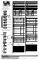
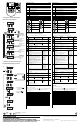
7. Close branch circuit disconnect to apply power.
If a fault code (Fxxx) is displayed instead, see the Fault Codes section on the next page.
8. Adjust the Speed Potentiometer according to your application.
9. Press Start and verify that the motor rotation is correct. (Table )
10. Press Stop . Disconnect power.
11. Refer to the User Manual to wire control I/O terminal block or program parameters to
achieve desired functionality. See the next page to program Basic Program group
parameters.
!
➀ ➁
➂
Drive enclosure is rated IP20, NEMA/UL Type Open.
Horizontal Clearance
between drives
Ambient Temperature
Minimum Maximum
0mm and greater -10 °C (14 °F) 40 °C (104 °F)
25mm and greater -10 °C (14 °F) 50 °C (122 °F)
➃
➄
➆
➅➇
VOLTS
AMPS
HERTZ
VOLTS
AMPS
HERTZ
Apply Power
(Blinks 3 times)
Apply Power
(Blinks 3 times)
➇
Terminal Description
R/L1, S/L2 1-Phase Input
R/L1, S/L2, T/L3 3-Phase Input
P1
, P2 DC Bus Inductor Connection
(1)
(1)
For Frame C only [5.5 kW (7.5 HP) ratings and higher].
U/T1 To Motor U/T1 Switch any two
motor leads to
change forward
direction.
V/T2 To Motor V/T2
W/T3 To Motor W/T3
DC+, DC- DC Bus Connection
(2)
(2)
Not applicable to 120V, 1-Phase drives.
BR+, BR- Dynamic Brake Resistor Connection
(1)
Safety Ground - PE
➇
日本語
こ の ク イ ッ ク ス タ ー ト に従 い、 PowerFlex 4M 可変周波数 AC ド ラ イ ブ の基本
的な設置、 配線お よ び基本パ ラ メ ー タ の設定を行な い ま す。 そ れ ら の タ ス ク
を完了する と、 内蔵キーパ ッ ド と ポテンシ ョ メータを使用して、 モータの始
動、 回転方向の確認 お よ び速度 の制御 を 行な う こ と が で き ま す。 本書は、
ユーザーズマニ ュ アルにかわるものではなく、 ド ラ イブの専門家のみを対象
にしています。
本書に は、 接地、 シ ー ル ド 、 I/O の 制御、 ESD ま た は CE 適合性に 対す る 指
示は記載していません。 ホームページ www.rockwellautomation.com/ literature
に記載されている取扱説明書 『PowerFlex 4M User Manual』
(Pub.No. 22F-UM001) 参照 し て く だ さ い。
一般的な注意
注意 : ド ラ イ ブ の設置、 立上げ、 お よ び以降の メ ン テ ナ ン ス の計画や実施す
る に は、 感電の危険、 安全対策、 電気工事規定お よ び関連機械へ の理解 と 注
意が必要で す。 こ の注意 を 守 ら な い と 、 人身事故が発生 し た り 機器が損傷す
る恐れがあ り ます。
注意 : ド ラ イ ブ に は、 メ イ ン電源 を 取 り 外 し た後に時間 を か け て 放電す る高
電圧 コ ン デ ン サ が内蔵 さ れ て い ま す。 ド う イ ブ で作業 を行な う 前 に、 メ イ ン
電源が う イ ン入 カ [R, S, T (L1, L2, L3)] か ら 絶縁 さ れ て い る か を確認 し て く だ
さ い。 コ ン デ ン サ が安全電圧レ ベ ル に な る ま で放電す る の に 3 分間待つ て く
だ さ い。 こ の注意 を 守 ら な い と 、 人身事故が発生 し て死に及ぶ 危険が あ ぃ ま
す。 LED の表示が暗 く な っ た こ と わ、 コ ン デ ン サ が安全電圧 レ ベ ル に ま で放
電されたこ と を示すわけではあいません。
注意 : パ ラ メ ー タ A451 [Auto Rstrt Tries] ま た は A433 [Start At PowerUp] を 不
適切な ア プ リ ケ ー シ ョ ン に使用す る と 、 装置の 損傷、 ま た は人体へ の危険を
招 く こ と が あ り ま す。 こ の機能 を 使用す る 際 に は、 当該地域、 国、 ま た は国
際間の法令、 規格、 規則、 ま た は産業界の ガ イ ド ラ イ ン に 配慮 し て く だ さ い 。
表 と表 を 参照し て く だ さ い 。 定格は kW と (HP) で す 。 寸法は mm と
( イ ン チ ) で す 。 重量は kg と ( ポ ン ド ) で す 。 本書で は 小数点が 使用さ れて
います。
*DIN レ ー ル取付け は、 フ レ ー ム A と B に対 し て の み適用 さ れ ま す。
1. 取付け の際、 最小取付け間隔 と 周囲温度に満 た す必要が あ り ま す。 平 ら
な垂直面に、 ねじ または DIN レールで真っ す ぐ に取付けます。 図 と
以降の表を参照し て く だ さ い。
2. ド ラ イ ブ が接地 さ れ て い な い か、 ま た は接地 さ れ た 抵抗配電シ ス テ ム に
取付け ら れ て い る場合、 接地ジ ャ ン パ へ の MOV( 金属酸化物バ リ ス タ )
を取り外す必要があ り ます。 ( 図 )
重要 : ジャンパを外した後、 ねじを締めます。
3. フ ィ ン ガ ガ ー ド を 開 き 、 電源端子台 に手 を 入れ て 作業 し ま す。 ( 図 )
重要 : リ モー ト デバ イ ス の制御端子へ の接続 (図 )では、
『ユーザー ズ マ ニ ュ ア ル』 の中の情報が必要です。 端子の機能は関連する
パラメータに応じて、設定しなければなりません。内蔵キーパッ ドを使
用してモー タ を始動する場合は、 ステ ッ プ 4 に進んで く だ さ い。
4. 電源 ラ イ ン を接続 し ま す。 ( 図 と表 )
5. モータから負荷を接続します。 モータの正しい回転を確認する準備をし
てください。
6. ス テ ッ プ 4 で行な っ た配線 を す べ て確認 し ま す。
7. 分岐回路切断を 閉 じ て、 電力 を 印加 し ま す。
フ ォ ル ト コ ー ド (Fxxx) が か わ り に表示 さ れ る 場合、 次ペ ー ジ の フ ォ ル ト
コードの項を参照して く ださい。
8. アプリケーショ ンに従って、速度ポテンショ メータを調整します。
9. [Start] を押して、 モータの回転が正しいことを確認します。
(表 )
10. [Stop] を 押 し ま す。 電源 を 切断 し ま す。
11. 『 ユーザーズマニュアル』 を参照して、制御I/O端子台を配線するか、パ
ラメータをプログラムして目的の機能を達成します。Basic Programグルー
プパラ メ ータ のプログラ ムについては、 次ページを参照し てく ださ い。
!
➀ ➁
➂
ド ラ イ ブ の ケ ー ス は、 定格 の IP20, NEMA/UL タ イ プ開放型で す。
ド ラ イ ブ間の水平方向の取付
け間隔
周囲温度
最小 最大
0mm 以上 -10°C (14°F)40°C (104°F)
25mm 以上 -10°C (14°F) 50°C (122°F)
➃
➄
➆
➅➇
VOLTS
AMPS
HERTZ
VOLTS
AMPS
HERTZ
Apply Power
(Blinks 3 times)
電源投入
3 回点滅
➇
端子 説明
R/L1, S/L2 単相入力
R/L1, S/L2, T/L3 3 相入力
P1, P2 DC バ ス イ ン ダ ク タ 接続
(1)
(1)
フレームCのみ [5.5 kW (7.5 HP) 定格以上 ]。
U/T1 モータ U/T1 へ モータのリード
線の ど れで も よ
いから 2本を切
換え て、 正方向
に変更し ます。
V/T2 モ ー タ V/T2 へ
W/T3 モ ー タ W/T3 へ
DC+, DC- DC バ ス 接続
(2)
(2)
120V, 単相 ド ラ イ ブ に は適用 し な い。
BR+, BR- ダ イ ナ ミ ッ ク ・ ブ レ ー キ ・ レ ジ ス タ 接続
(1)
安全接地 - PE
➇