Adjustable Frequency AC Drive FRN 1.xx - 2.xx User Manual www.abpowerflex.
Important User Information Solid state equipment has operational characteristics differing from those of electromechanical equipment. Safety Guidelines for the Application, Installation and Maintenance of Solid State Controls (Publication SGI-1.1 available from your local Rockwell Automation sales office or online at http://www.rockwellautomation.com/literature) describes some important differences between solid state equipment and hard-wired electromechanical devices.
Summary of Changes The information below summarizes the changes to the PowerFlex 4M User Manual since the July 2008 release. Manual Updates Description of New or Updated Information Minimum Enclosure Volume column and new footnotes added. Drive, Fuse & Circuit Breaker Ratings topic updated. Electronic Motor Overload Protection description updated. Page(s) 1-8, A-2 A-1 A-4 The information below summarizes the changes to the PowerFlex 4M User Manual since the August 2007 release.
soc-2 The information below summarizes the changes to the PowerFlex 4M User Manual since the February 2007 release. Manual Updates Description of New or Updated Information Input description and attention text for Multiple Digital Input Connection example corrected. Description for option 21 of parameter t221 [Relay Out Sel] corrected. Invalid catalog number for L Type Filter deleted. Graphic for the “Connecting an RS-485 Network” section corrected PowerFlex 4M Adjustable Frequency Drive FRN 1.xx - 2.
Table of Contents Preface Overview Who Should Use this Manual? . . . . . . . . . Reference Materials . . . . . . . . . . . . . . . . . Manual Conventions . . . . . . . . . . . . . . . . . Drive Frame Sizes . . . . . . . . . . . . . . . . . . . General Precautions . . . . . . . . . . . . . . . . . Catalog Number Explanation . . . . . . . . . . Chapter 1 P-1 P-1 P-2 P-2 P-3 P-4 Installation/Wiring Opening the Cover . . . . . . . . . . . . . . . . . . 1-1 Mounting Considerations . . . . . . . . . . . . .
ii Table of Contents Appendix C RS485 (DSI) Protocol Network Wiring . . . . . . . . . . . . . . . . . . . . . Parameter Configuration . . . . . . . . . . . . . . Supported Modbus Function Codes . . . . . Writing (06) Logic Command Data. . . . . . Writing (06) Reference . . . . . . . . . . . . . . . Reading (03) Logic Status Data. . . . . . . . . Reading (03) Feedback . . . . . . . . . . . . . . . Reading (03) Drive Error Codes . . . . . . . . Reading (03) and Writing (06) Drive Parameters . . . . . . . .
Preface Overview The purpose of this manual is to provide you with the basic information needed to install, start-up and troubleshoot the PowerFlex 4M Adjustable Frequency AC Drive. For information on… Who Should Use this Manual? Reference Materials Manual Conventions Drive Frame Sizes General Precautions Catalog Number Explanation See page… P-1 P-1 P-2 P-2 P-3 P-4 Who Should Use this Manual? This manual is intended for qualified personnel.
P-2 Overview Manual Conventions • In this manual we refer to the PowerFlex 4M Adjustable Frequency AC Drive as: drive, PowerFlex 4M or PowerFlex 4M Drive.
Overview P-3 General Precautions ! ATTENTION: To avoid an electric shock hazard, verify that the voltage on the bus capacitors has discharged before performing any work on the drive. Measure the DC bus voltage at the –DC and +DC terminals on the Power Terminal Block (refer to Chapter 1 Power Terminal descriptions). The voltage must be zero. Darkened LEDs or a darkened LCD display is not an indication that capacitors have discharged to safe voltage levels.
P-4 Overview Catalog Number Explanation 1-3 4 5 6-8 22F - D 8P7 Drive Dash Voltage Rating Rating 9 10 11 N 1 1 Enclosure HIM Emission Class Code 22F PowerFlex 4M Code V A B D Voltage 120V AC 240V AC 240V AC 480V AC 12 13-14 3 AA Type Optional Code Version 3 No Brake IGBT 4 Standard Ph.
Chapter 1 Installation/Wiring This chapter provides information on mounting and wiring the PowerFlex 4M Drive. For information on… Opening the Cover Mounting Considerations AC Supply Source Considerations See page 1-1 1-2 1-3 General Grounding Requirements 1-5 For information on… Fuses and Circuit Breakers Power Wiring I/O Wiring Recommendations EMC Instructions See page 1-7 1-9 1-13 1-21 Most start-up difficulties are the result of incorrect wiring.
1-2 Installation/Wiring Mounting Considerations • Mount the drive upright on a flat, vertical and level surface. – Install on 35 mm DIN Rail (for frames A and B). or – Install with screws. Table 1.A Screw Mounting Recommendations • • • Minimum Panel Thickness Screw Size Mounting Torque 1.9 mm (0.0747 in.) 1.56-1.96 N-m (14-17 lb.-in.) M4 (#8-32) Protect the cooling fan by avoiding dust or metallic particles. Do not expose to a corrosive atmosphere. Protect from moisture and direct sunlight.
Installation/Wiring 1-3 Storage • • • Store within an ambient temperature range of -40° to +85°C. Store within a relative humidity range of 0% to 95%, non-condensing. Do not expose to a corrosive atmosphere. AC Supply Source Considerations Ungrounded Distribution Systems ! ATTENTION: PowerFlex 4M drives contain protective MOVs that are referenced to ground. These devices must be disconnected if the drive is installed on an ungrounded or resistive grounded distribution system.
1-4 Installation/Wiring Figure 1.2 Phase to Ground MOV Removal R/L1 Three-Phase AC Input S/L2 T/L3 Jumper 1 2 3 4 Input Power Conditioning The drive is suitable for direct connection to input power within the rated voltage of the drive (see Appendix A). Listed in Table 1.C are certain input power conditions which may cause component damage or reduction in product life. If any of the conditions exist, as described in Table 1.
Installation/Wiring 1-5 General Grounding Requirements The drive Safety Ground (PE) must be connected to system ground. Ground impedance must conform to the requirements of national and local industrial safety regulations and/or electrical codes. The integrity of all ground connections should be periodically checked. Figure 1.
1-6 Installation/Wiring Shield Termination - SHLD Either of the safety ground terminals located on the power terminal block provides a grounding point for the motor cable shield. The motor cable shield connected to one of these terminals (drive end) should also be connected to the motor frame (motor end). Use a shield terminating or EMI clamp to connect the shield to the safety ground terminal. The conduit box option may be used with a cable clamp for a grounding point for the cable shield.
Installation/Wiring 1-7 Fuses and Circuit Breakers The PowerFlex 4M does not provide branch short circuit protection. This product should be installed with either input fuses or an input circuit breaker. National and local industrial safety regulations and/or electrical codes may determine additional requirements for these installations.
1-8 Installation/Wiring Table 1.D Minimum Recommended Branch Circuit Protective Devices Voltage Rating Drive Rating kW (HP) Fuse Rating(1) 140M(2) (3) Amps Catalog No. Recommended Min. Enclosure MCS Contactors Volume(4) Catalog No. Inches3 120V AC – 1-Phase 0.2 (0.25) 0.4 (0.5) 0.75 (1.0) 1.1 (1.5) 10 15 30 40 140M-C2E-C10 140M-C2E-C16 140M-D8E-C20 140M-F8E-C32 100-C09 100-C12 100-C23 100-C30 1655 1655 1655 1655 240V AC – 1-Phase 0.2 (0.25) 0.4 (0.5) 0.75 (1.0) 1.5 (2.0) 2.2 (3.
Installation/Wiring 1-9 Power Wiring ! ! ATTENTION: National Codes and standards (NEC, VDE, BSI, etc.) and local codes outline provisions for safely installing electrical equipment. Installation must comply with specifications regarding wire types, conductor sizes, branch circuit protection and disconnect devices. Failure to do so may result in personal injury and/or equipment damage.
1-10 Installation/Wiring Shielded Location Standard (Option 1) Rating/Type 600V, 75°C or 90°C (167°F or 194°F) RHH/RHW-2 Belden 29501-29507 or equivalent Standard (Option 2) Tray rated 600V, 75°C or 90°C (167°F or 194°F) RHH/RHW-2 Shawflex 2ACD/3ACD or equivalent Class I & II; Tray rated 600V, 75°C or Division I & II 90°C (167°F or 194°F) RHH/RHW-2 Description • Four tinned copper conductors with XLPE insulation • Foil shield and tinned copper drain wire with 85% braid coverage • PVC jacket • Three ti
Installation/Wiring 1-11 Power Terminal Block The drive utilizes a finger guard over the power wiring terminals. To remove: 1. Press in and hold the locking tab. 2. For the finger guard on the top of the drive, slide it down and out. For the finger guard at the bottom of the drive, slide it up and out. Replace the finger guard when wiring is complete. Figure 1.
1-12 Installation/Wiring Terminal DC+(2), DC-(2) BR+(1), BR-(1) (1) (2) Description DC Bus Connection Dynamic Brake Resistor Connection Safety Ground - PE For Frame C only [5.5 kW (7.5 HP) ratings and higher]. Not applicable to 120 V, 1-Phase drives. Table 1.F Power Terminal Block Specifications Frame Maximum Wire Size (1) Minimum Wire Size (1) Torque A 3.3 mm2 (12 AWG) B C (1) 8.4 mm 2 (8 AWG) 2 13.3 mm (6 AWG) 0.8 mm2 (18 AWG) 1.4-1.6 N-m (12-14 lb.-in.) 0.8 mm2 (18 AWG) 1.6-1.
Installation/Wiring 1-13 I/O Wiring Recommendations Important points to remember about I/O wiring: • • • Always use copper wire. Wire with an insulation rating of 600V or greater is recommended. Control and signal wires should be separated from power wires by at least 0.3 meters (1 foot). Important: I/O terminals labeled “Common” are not referenced to the safety ground (PE) terminal and are designed to greatly reduce common mode interference.
1-14 Installation/Wiring Figure 1.5 Control Wiring Block Diagram (1) Important: I/O Terminal 01 is always a coast to stop input except when P106 [Start Source] is set to “3-Wire” control. In three wire control, I/O Terminal 01 is controlled by P107 [Stop Mode]. All other stop sources are controlled by P107 [Stop Mode]. P106 [Start Source] Important: The drive is shipped with a jumper installed between I/O Terminals 01 and 11. Remove this jumper when using I/O Terminal 01 as a stop or enable input.
Installation/Wiring No. Signal 12 +10V DC 13 0-10V In (3) Default Description Param. – Drive supplied power for 0-10V external potentiometer. Maximum output current is 15mA. P108 Not Active For external 0-10V input supply (input impedance = 100k ohm) or potentiometer wiper. P108 14 Analog Common – For 0-10V In or 4-20mA In. Electronically isolated with analog inputs from digital I/O. 15 4-20mA In (3) Not Active For external 4-20mA input supply (input impedance = 250 ohm).
1-16 Installation/Wiring Input Connection Example 2 Wire SRC Control Internal Supply (SRC) Non-Reversing P106 [Start Source] = 2, 3 11 or 4 Input must be active for Stop-Run the drive to run. When input is opened, the drive will stop as specified by P107 [Stop Mode]. If desired, a User Supplied 24V DC power source can be used. Refer to the “External Supply (SRC)” example.
Installation/Wiring Input 3 Wire SRC Control Non-Reversing P106 [Start Source] = 1 A momentary input will start the drive. A stop input to I/O Terminal 01 will stop the drive as specified by P107 [Stop Mode]. Connection Example Internal Supply (SRC) Stop 11 1-17 External Supply (SRC) Stop 01 02 01 02 Start Start +24V 04 Common Each digital input draws 6 mA.
1-18 Installation/Wiring Typical Multiple Drive Connection Examples Input Connection Example Multiple Digital 02 04 02 Input Connections Customer Inputs can be wired per External Supply (SRC) examples on page 1-16. Customer Inputs 04 02 04 02 04 Optional Ground Connection When connecting a single input such as Run, Stop, Reverse or Preset Speeds to multiple drives, it is important to connect I/O Terminal 04 common together for all drives.
Installation/Wiring 1-19 Start and Speed Reference Control The drive speed command can be obtained from a number of different sources. The source is normally determined by P108 [Speed Reference]. However, when t201 or t202 Digital Inx Sel is set to option 2, 4, 5 or 6, and the digital input is active, t201 or t202 will override the speed reference commanded by P108 [Speed Reference]. See the chart below for the override priority.
1-20 Installation/Wiring Accel/Decel Selection The selection of Accel/Decel rates can be made through digital inputs, RS485 (DSI) communications and/or parameters. Jog Input Enabled and Active: t201 or t202 = 2 Yes A405 [Jog Accel/Decel] used. Yes Active when A401 [Accel Time 2]/A402 [Decel Time 2] is selected by RS485 (DSI) port.
Installation/Wiring 1-21 EMC Instructions CE Conformity Conformity with the Low Voltage (LV) Directive and Electromagnetic Compatibility (EMC) Directive has been demonstrated using harmonized European Norm (EN) standards published in the Official Journal of the European Communities. PowerFlex Drives comply with the EN standards listed below when installed according to the User Manual. CE Declarations of Conformity are available online at: http://www.ab.com/certification/ce/docs.
1-22 Installation/Wiring Essential Requirements for CE Compliance Conditions 1-3 listed below must be satisfied for PowerFlex drives to meet the requirements of EN61800-3. 1. Grounding as described in Figure 1.6. Refer to page 1-6 for additional grounding recommendations. 2. Output power, control (I/O) and signal wiring must be braided, shielded cable with a coverage of 75% or better, metal conduit or equivalent attenuation. 3. Allowable cable length in Table 1.I is not exceeded. Table 1.
Installation/Wiring 1-23 EN61000-3-2 • • 0.75 kW (1 HP) 240V 1-Phase and 3-Phase drives and 0.4 kW (0.5 HP) 240V 1-Phase drives are suitable for installation on a private low voltage power network. Installations on a public low voltage power network may require additional external harmonic mitigation. Other drive ratings meet the current harmonic requirements of EN61000-3-2 without additional external mitigation. PowerFlex 4M Adjustable Frequency Drive FRN 1.xx - 2.
1-24 Installation/Wiring Notes: PowerFlex 4M Adjustable Frequency Drive FRN 1.xx - 2.
Chapter 2 Start Up This chapter describes how to start up the PowerFlex 4M Drive. To simplify drive setup, the most commonly programmed parameters are organized in a single Basic Program Group. Important: Read the General Precautions section before proceeding. ! ATTENTION: Power must be applied to the drive to perform the following start-up procedures. Some of the voltages present are at incoming line potential.
2-2 Start Up Applying Power to the Drive ❏ 6. Apply AC power and control voltages to the drive. ❏ 7. Familiarize yourself with the integral keypad features (see page 2-3) before setting any Program Group parameters. Start, Stop, Direction and Speed Control Factory default parameter values allow the drive to be controlled from the integral keypad. No programming is required to start, stop, change direction and control speed directly from the integral keypad.
Start Up 2-3 Integral Keypad Menu Description Display Group (View Only) Consists of commonly viewed drive operating conditions. Basic Program Group Consists of most commonly used programmable functions. Terminal Block Group Consists of programmable functions for control terminals. Communications Group Consists of programmable functions for communications. Advanced Program Group Consists of remaining programmable functions.
2-4 Start Up No. LED ➒ LED State Speed Potentiometer Description Used to control speed of drive. Default is active. Controlled by parameter P108 [Speed Reference]. Start Used to start the drive. Default is active. Controlled by parameter P106 [Start Source]. Used to reverse direction of the drive. Default is active. Controlled by parameters P106 [Start Source] and A434 [Reverse Disable]. Used to stop the drive or clear a fault. This key is always active. Controlled by parameter P107 [Stop Mode].
Start Up Step Key(s) 6. Press Enter or Sel to view the value of a parameter. If you do not want to edit the value, press Esc to return to the parameter number. 7. Press Enter or Sel to enter program mode to edit the parameter value. The rightmost digit will flash and the Program LED will illuminate if the parameter can be edited. 8. Press the Up Arrow or Down Arrow to change the parameter value. If desired, press Sel to move from digit to digit or bit to bit.
2-6 Start Up Notes: PowerFlex 4M Adjustable Frequency Drive FRN 1.xx - 2.
Chapter 3 Programming and Parameters Chapter 3 provides a complete listing and description of the PowerFlex 4M parameters. Parameters are programmed (viewed/edited) using the integral keypad. As an alternative, programming can also be performed using DriveExplorer™ or DriveExecutive™ software, a personal computer and a serial converter module. Refer to Appendix B for catalog numbers.
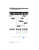
3-2 Programming and Parameters Parameter Organization Group Parameters Basic Display Displa y Gro up Basic Program B Prograasic m Gro up Terminal Block Ad Progravanced m Gro up Communications Ad Progravanced m Gro up Advanced Program Ad Progravanced m Gro up Output Freq Commanded Freq Output Current Output Voltage DC Bus Voltage Drive Status Fault 1 Code Fault 2 Code Fault 3 Code Process Display d001 d002 d003 d004 d005 d006 d007 d008 d009 d010 Control Source Contrl In Status Dig In Status Co
Programming and Parameters 3-3 Display Group d001 [Output Freq] Related Parameter(s): d002, d010, P104, P105, P108 Output frequency present at T1, T2 & T3 (U, V & W). Values Default Read Only Min/Max: 0.0/P105 [Maximum Freq] Display: 0.1 Hz d002 [Commanded Freq] Related Parameter(s): d001, d013, P104, P105, P108 Value of the active frequency command. Displays the commanded frequency even if the drive is not running. Important: The frequency command can come from a number of sources.
3-4 Programming and Parameters Display Group (continued) d006 [Drive Status] Related Parameter(s): A434 Present operating condition of the drive. Running Forward Accelerating Decelerating Values 1 = Condition True, 0 = Condition False Bit 0 Bit 1 Bit 2 Bit 3 Default Read Only Min/Max: 0/1 Display: 1 d007 [Fault 1 Code] d008 [Fault 2 Code] d009 [Fault 3 Code] A code that represents a drive fault.
Programming and Parameters 3-5 Display Group (continued) d012 [Control Source] Related Parameter(s): P106, P108, t201, t202 Displays the active source of the Start Command and Speed Command which are normally defined by the settings of P106 [Start Source] and P108 [Speed Reference] but may be overridden by digital inputs. Refer to the flowcharts on pages 1-19 and 1-20 for details.
3-6 Programming and Parameters Display Group (continued) d014 [Dig In Status] Related Parameter(s): t201, t202 Status of the control terminal block digital inputs. 1 = Input Present, 0 = Input Not Present Digital In1 Sel (I/O Terminal 05) Bit 0 Digital In2 Sel (I/O Terminal 06) Bit 1 Reserved Bit 2 Reserved Bit 3 Values Default Read Only Min/Max: 0/1 Display: 1 d015 [Comm Status] Related Parameter(s): C302 - C306 Status of the communications ports.
Programming and Parameters 3-7 Display Group (continued) d018 [Elapsed Run Time] Accumulated time drive is outputting power. Time is displayed in 10-hour increments. Values Default Read Only Min/Max: 0/9999 Hrs Display: 1 (= 10 Hrs) d019 [Testpoint Data] Related Parameter(s): A459 The present value of the function selected in A459 [Testpoint Sel].
3-8 Programming and Parameters Basic Program Group P101 [Motor NP Volts] Related Parameter(s): d004, A453 Stop drive before changing this parameter. Set to the motor nameplate rated voltage. Values Default Based on Drive Rating Min/Max: 20/Drive Rated Voltage Display: 1 VAC P102 [Motor NP Hertz] Related Parameter(s): A453, A444 Stop drive before changing this parameter. Set to the motor nameplate rated frequency.
Programming and Parameters 3-9 Basic Program Group (continued) P106 [Start Source] Related Parameter(s): d012, P107 Stop drive before changing this parameter. Sets the control scheme used to start the drive. Refer to Start and Speed Reference Control on page 1-19 for details about how other drive settings can override the setting of this parameter.
3-10 Programming and Parameters Basic Program Group (continued) P107 [Stop Mode] Related Parameter(s): P106, A418, A425, A427, C304 Active stop mode for all stop sources [e.g. keypad, run forward (I/O Terminal 02), run reverse (I/O Terminal 03), RS485 port] except as noted below. Important: I/O Terminal 01 is always a coast to stop input except when P106 [Start Source] is set for “3-Wire” control. When in three wire control, I/O Terminal 01 is controlled by P107 [Stop Mode].
Programming and Parameters 3-11 Basic Program Group (continued) P108 [Speed Reference] Related Parameter(s): d001, d002, d012, P109, P110, t201, t202, A409, A410-A413, t211, t212, t213, t214 Sets the source of the speed reference to the drive. The drive speed command can be obtained from a number of different sources. The source is normally determined by P108 [Speed Reference].
3-12 Programming and Parameters Basic Program Group (continued) P110 [Decel Time 1] Related Parameter(s): P108, P109, t201, t202, A402, A410-A413 Sets the rate of deceleration for all speed decreases. Maximum Freq = Decel Rate Decel Time Values Default 10.0 Secs Min/Max: 0.1/600.0 Secs Display: 0.
Programming and Parameters 3-13 Terminal Block Group t201 [Digital In1 Sel] (I/O Terminal 5) t202 [Digital In2 Sel] Related Parameter(s): d012, d014, P108, P109, P110, t211-t214, A401, A402, A404, A405, A410-A413 Stop drive before changing this parameter. (I/O Terminal 6) Selects the function for the digital inputs. Refer to the flowchart on page 1-19 for more information on speed reference control priority.
3-14 Programming and Parameters t201 & 13 “10V In Ctrl” t202 Options 14 “20mA In Ctrl” (Cont.) Selects 0-10V or ±10V control as the frequency reference. Start source is not changed. Selects 4-20mA control as the frequency reference. Start source is not changed. 15 “Anlg Invert” Inverts the scaling of the analog input levels set in t211 [Anlg In 0-10V Lo] and t212 [Anlg In 0-10V Hi] or t213 [Anlg In4-20mA Lo] and t214 [Anlg In4-20mA Hi].
Programming and Parameters 3-15 Terminal Block Group (continued) t214 [Anlg In4-20mA Hi] Related Parameter(s): d021, P105, P108, t201, t202 Sets the analog input level that corresponds to P105 [Maximum Freq] if a 4-20mA input is used by P108 [Speed Reference]. Analog inversion can be accomplished by setting this value smaller than t213 [Anlg In4-20mA Lo] or by setting t201 - t202 [Digital Inx Sel] to option 15 “Anlg Invert”. Values Default 100.0% Min/Max: 0.0/ 100.0% Display: 0.
3-16 Programming and Parameters Terminal Block Group (continued) t222 [Relay Out Level] 32 Related Parameter(s): t221 32 bit parameter. Sets the trip point for the digital output relay if the value of t221 [Relay Out Sel] is 6, 7, 8, 10 or 11. t221 Setting 6 7 8 10 11 Values t222 Min/Max 0/400 Hz 0/180% 0/815 Volts 0/100% 0/1 Default 0.0 Min/Max: As above Display: 0.1 PowerFlex 4M Adjustable Frequency Drive FRN 1.xx - 2.
Programming and Parameters 3-17 Communications Group C301 [Language] Selects the language displayed by the remote communications option. Options 1 “English” (Default) 2 “Second Lang” (Reserved) C302 [Comm Data Rate] Related Parameter(s): d015 Sets the serial port rate for the RS485 (DSI) port. Important: Power to drive must be cycled before any changes will affect drive operation. Options 0 “1200” 1 “2400” 2 “4800” 3 “9600” (Default) 4 “19.2K” 5 “38.
3-18 Programming and Parameters Communications Group (continued) C305 [Comm Loss Time] Related Parameter(s): d015, C304 Sets the time that the drive will remain in communication loss before implementing the option selected in C304 [Comm Loss Action]. Values Default 5.0 Secs Min/Max: 0.1/ 60.0 Secs Display: 0.1 Secs C306 [Comm Format] Selects the protocol (RTU only), data bits (8 data bits only), parity (None, Even, Odd), and stop bits (1 stop bit only) used by the RS485 port on the drive.
Programming and Parameters 3-19 Advanced Program Group A401 [Accel Time 2] Related Parameter(s): P109 When active, sets the rate of acceleration for all speed increases except jog. Refer to the flowchart on page 1-20 for details. Maximum Freq = Accel Rate Accel Time Values Default 20.0 Secs Min/Max: 0.0/600.0 Secs Display: 0.
3-20 Programming and Parameters Advanced Program Group (continued) A403 [S Curve %] Sets the percentage of acceleration or deceleration time that is applied to the ramp as S Curve. Time is added, 1/2 at the beginning and 1/2 at the end of the ramp. Values Default 0% (Disabled) Min/Max: 0/100% Display: 1% Example: Accel Time = 10 Seconds S Curve Setting = 50% S Curve Time = 10 × 0.5 = 5 Seconds Total Time = 10 + 5 = 15 Seconds 50% S Curve Target Target/2 1/2 S Curve Time 2.
Programming and Parameters 3-21 Advanced Program Group (continued) A410 [Preset Freq 0](1) A411 [Preset Freq 1] A412 [Preset Freq 2] A413 [Preset Freq 3] Values Related Parameter(s): P108, P109, P110, t201, t202, A401, A402 A410 Default A411 Default A412 Default A413 Default 0.0 Hz 5.0 Hz 10.0 Hz 20.0 Hz Min/Max: 0.0/400.0 Hz Display: 0.1 Hz Provides a fixed frequency command value when t201 - t202 [Digital Inx Sel] is set to 4 “Preset Frequencies”.
3-22 Programming and Parameters Advanced Program Group (continued) A419 [Skip Freq Band] Related Parameter(s): A418 Determines the bandwidth around A418 [Skip Frequency]. A419 [Skip Freq Band] is applied above and below the actual skip frequency. See the diagram below. A setting of 0.0 disables this parameter. Values Default: 0.0 Hz Min/Max: 0.0/30.0 Hz Display: 0.
Programming and Parameters 3-23 Advanced Program Group (continued) A425 [DC Brake Level] Related Parameter(s): P107, A418 Defines the maximum DC brake current, in amps, applied to the motor when P107 [Stop Mode] is set to either “Ramp” or “DC Brake”. Values Default Drive Rated Amps × 0.05 Min/Max: 0.0/(Drive Rated Amps × 1.8) Display: 0.
3-24 Programming and Parameters Advanced Program Group (continued) A428 [DB Duty Cycle] Related Parameter(s): A427 Stop drive before changing this parameter. Selects the duty cycle allowed for an external dynamic braking resistor when A427 [DB Resistor Sel] is set to 3. This parameter applies only to Frame C drives. Values Default 5% Min/Max: 1/99% Display: 1% A433 [Start At PowerUp] Stop drive before changing this parameter.
Programming and Parameters 3-25 Advanced Program Group (continued) A436 [Compensation] Enables/disables correction options that may improve problems with motor instability. Options 0 “Disabled” 1 “Electrical” (Default) Some drive/motor combinations have inherent instabilities which are exhibited as non-sinusodial motor currents. This setting attempts to correct this condition. 2 “Mechanical” Some motor/load combinations have mechanical resonances which can be excited by the drive current regulator.
3-26 Programming and Parameters Advanced Program Group (continued) A440 [Process Factor] Related Parameter(s): d010 Scales the value displayed by d010 [Process Display]. Output Process Process Freq x Factor = Display Values Default 30.0 Min/Max: 0.1/999.9 Display: 0.1 A441 [Bus Reg Mode] Controls the operation of the drive voltage regulation, which is normally operational at deceleration or when the bus voltage rises.
Programming and Parameters 3-27 Advanced Program Group (continued) A446 [PWM Frequency] Sets the carrier frequency for the PWM output waveform. The chart below provides derating guidelines based on the PWM frequency setting. Important: Ignoring derating guidelines can cause reduced drive performance. % Output Curent (A) Values 100 96 92 88 84 80 76 72 68 64 60 56 52 1 Default 4.0 kHz Min/Max: 2.0/10.0 kHz Display: 0.
3-28 Programming and Parameters Advanced Program Group (continued) A450 [Fault Clear] Stop drive before changing this parameter. Resets a fault and clears the fault queue. Used primarily to clear a fault over network communications. Options 0 “Ready/Idle” (Default) 1 “Reset Fault” 2 “Clear Buffer” (Parameters d007-d009 [Fault x Code]) A451 [Auto Rstrt Tries] Sets the maximum number of times the drive attempts to reset a fault and restart. Clear a Type 1 fault and restart the drive. 1.
Programming and Parameters 3-29 Advanced Program Group (continued) A453 [Boost Select] Related Parameter(s): d004, P101, P102 Sets the boost voltage (% of P101 [Motor NP Volts]) and redefines the Volts per Hz curve.(1) (1) Drive may add additional voltage unless option 5 is selected. Options 1 “30.0, VT” 2 “35.0, VT” Variable Torque 3 “40.0, VT” 4 “45.0, VT” 5 “0.0 no IR” 6 “0.0” 7 “2.5, CT” [Default for 3.7, 5.5, 7.5 & 11.0 kW (5.0, 7.5, 10.0 & 15.0 HP) Drives] 8 “5.
3-30 Programming and Parameters Advanced Program Group (continued) A457 [Maximum Voltage] Sets the highest voltage the drive will output. Values Default Drive Rated Volts Min/Max: 20/Drive Rated Volts Display: 1 VAC A458 [Program Lock] Protects parameters against change by unauthorized personnel. Options 0 “Unlocked” (Default) 1 “Locked” A459 [Testpoint Sel] Used by Rockwell Automation field service personnel.
Programming and Parameters 3-31 Parameter Cross Reference – by Name Parameter Name Number Group Page Parameter Name Number Group Page Accel Time 1 Accel Time 2 Analog In 0-10V Analog In 4-20mA Anlg In 0-10V Hi Anlg In 0-10V Lo Anlg In4-20mA Hi Anlg In4-20mA Lo Auto Rstrt Delay Auto Rstrt Tries Boost Select Bus Reg Mode Comm Data Rate Comm Format Comm Loss Action Comm Loss Time Comm Node Addr Comm Status Comm Write Mode Commanded Freq Compensation Contrl In Status Control Source Control SW Ver Curren
3-32 Programming and Parameters Notes: PowerFlex 4M Adjustable Frequency Drive FRN 1.xx - 2.
Chapter 4 Troubleshooting Chapter 4 provides information to guide you in troubleshooting the PowerFlex 4M drive. Included is a listing and description of drive faults (with possible solutions, when applicable). For information on… Drive Status Faults See page… For information on… 4-1 Fault Descriptions 4-1 Common Symptoms and Corrective Actions See page… 4-3 4-5 Drive Status The condition or state of your drive is constantly monitored. Any changes will be indicated through the integral keypad.
4-2 Troubleshooting Fault Indication Condition Display Drive is indicating a fault. The integral keypad provides visual notification of a fault condition by displaying the following. • Flashing fault number • Flashing fault indicator Press the Escape key to regain control of the integral keypad. Manually Clearing Faults Step Key(s) 1. Press Esc to acknowledge the fault. The fault information will be removed so that you can use the integral keypad.
Troubleshooting 4-3 Fault Descriptions No. Fault Type(1) Table 4.A Fault Types, Descriptions and Actions Description F2 Auxiliary Input ➀ Auxiliary input interlock is open. F3 Power Loss ➁ F4 UnderVoltage ➀ F5 OverVoltage ➀ F6 Motor Stalled ➀ F7 Motor Overload ➀ F8 Heatsink OvrTmp ➀ F12 HW OverCurrent ➁ F13 Ground Fault ➁ (1) Action 1. Check remote wiring. 2. Verify communications programming for intentional fault. Excessive DC Bus voltage ripple. 1.
Troubleshooting Type(1) 4-4 No. Fault Description Action F33 Auto Rstrt Tries ➁ Drive unsuccessfully attempted to reset a fault and resume running for the programmed number of A451 [Auto Rstrt Tries]. A phase to ground fault has been detected between the drive and motor in this phase. Correct the cause of the fault and manually clear.
Troubleshooting 4-5 Common Symptoms and Corrective Actions Motor does not Start. Cause(s) No output voltage to the motor. Indication None Improper boost setting at initial start-up. Drive is Faulted None Flashing red status light Corrective Action Check the power circuit. • Check the supply voltage. • Check all fuses and disconnects. Check the motor. • Verify that the motor is connected properly. Check the control input signals. • Verify that a Start signal is present.
4-6 Troubleshooting Drive does not Start from Start or Run Inputs wired to the terminal block. Cause(s) Drive is Faulted Indication Flashing red status light None Incorrect programming. • P106 [Start Source] is set to option 0 “Keypad” or option 5 “RS485 (DSI) Port”. • t201 - t202 [Digital Inx Select] is set to option 5 “Local” and the input is active. Incorrect input wiring. None See 1-15 for wiring examples. • 2 wire control requires Run Forward, Run Reverse or Jog input.
Troubleshooting 4-7 Motor and/or drive will not accelerate to commanded speed. Cause(s) Indication Acceleration time is excessive. None Excess load or short None acceleration times force the drive into current limit, slowing or stopping acceleration. Speed command source or value is not as expected. None Programming is preventing the None drive output from exceeding limiting values. Corrective Action Reprogram P109 [Accel Time 1] or A401 [Accel Time 2].
4-8 Troubleshooting Notes: PowerFlex 4M Adjustable Frequency Drive FRN 1.xx - 2.
Appendix A Supplemental Drive Information For information on… Drive, Fuse & Circuit Breaker Ratings Specifications See page… A-1 A-2 Drive, Fuse & Circuit Breaker Ratings The tables on the following pages provide recommended AC line input fuse and circuit breaker information. See Fusing and Circuit Breakers below for UL and IEC requirements. Sizes listed are the recommended sizes based on 40 °C (104 °F) and the U.S. N.E.C. Other country, state or local codes may require different ratings.
A-2 Supplemental Drive Information Specifications Drive Ratings Input Ratings Branch Circuit Protection Voltage 140M Motor Min. Enclosure kW (HP) Amps Range kVA Amps Fuses Protectors(2) (3) Contactors Volume(4) (in.3) 100 - 120V AC (±10%) – 1-Phase Input, 0 - 230V 3-Phase Output Catalog Number 22F-V1P6N103 22F-V2P5N103 22F-V4P5N103 22F-V6P0N103 Output Ratings 0.2 (0.25) 0.4 (0.5) 0.75 (1.0) 1.1 (1.5) 1.6 2.5 4.5 6.0 90-126 90-126 90-126 90-126 0.8 1.1 2.2 2.9 6.4 9.0 18.0 24.
Supplemental Drive Information (4) A-3 When using a Manual Self-Protected (Type E) Combination Motor Controller, the drive must be installed in a ventilated or non-ventilated enclosure with the minimum volume specified in this column. Application specific thermal considerations may require a larger enclosure. Approvals Input/Output Ratings Output Frequency: 0-400 Hz (Programmable) Efficiency: 97.
A-4 Supplemental Drive Information Category Environment Specification Altitude: Maximum Surrounding Air Temperature without derating: IP20: IP20 zero stacking: Cooling Method Convection: Fan: Storage Temperature: Atmosphere: Control Relative Humidity: Shock (operating): Vibration (operating): Carrier Frequency Frequency Accuracy Digital Input: Analog Input: Speed Regulation - Open Loop with Slip Compensation: Stop Modes: Acceleration/Deceleration: Intermittent Overload: Electronic Motor Overload Prot
Supplemental Drive Information A-5 PowerFlex 4M Estimated Watts Loss (Rated Load, Speed & PWM) Voltage 100–120V, 1-Phase 200–240V, 1-Phase 200–240V, 3-Phase 380–480V, 3-Phase kW (HP) 0.2 (0.25) 0.4 (0.5) 0.75 (1.0) 1.1 (1.5) 0.2 (0.25) 0.4 (0.5) 0.75 (1.0) 1.5 (2.0) 2.2 (3.0) 0.2 (0.25) 0.4 (0.5) 0.75 (1.0) 1.5 (2.0) 2.2 (3.0) 3.7 (5.0) 5.5 (7.5) 7.5 (10) 0.4 (0.5) 0.75 (1.0) 1.5 (2.0) 2.2 (3.0) 3.7 (5.0) 5.5 (7.5) 7.
A-6 Supplemental Drive Information Notes: PowerFlex 4M Adjustable Frequency Drive FRN 1.xx - 2.
Appendix B Accessories and Dimensions For information on… Product Selection Product Dimensions See page B-1 B-6 Product Selection Table B.A Catalog Number Description 22F Drive D 8P7 N 1 1 3 Voltage Rating Rating Enclosure HIM Emission Class Type Table B.B PowerFlex 4M Drives Catalog Number Drive Ratings Input Voltage 120V 50/60 Hz 1-Phase 240V 50/60 Hz 1-Phase 240V 50/60 Hz 1-Phase With Integral EMC Filter(1) 240V 50/60 Hz 3-Phase 480V 50/60 Hz 3-Phase kW 0.2 0.4 0.75 1.1 0.2 0.4 0.
B-2 Accessories and Dimensions Catalog Number Drive Ratings Input Voltage 480V 50/60 Hz 3-Phase With Integral EMC Filter(2) (1) kW 0.4 0.75 1.5 2.2 3.7 5.5 7.5 11.0 HP 0.5 1.0 2.0 3.0 5.0 7.5 10.0 15.0 Output Current (A) 1.5 2.5 4.2 6.0 8.7 13.0 18.0 24.
Accessories and Dimensions B-3 Table B.D Bulletin 1321-3R Series Line Reactors Input Voltage kW 240V 50/60 Hz 0.2 3-Phase 0.4 HP Maximum Fundamental Continuous Watts Amps Amps Inductance Loss 0.25 2 3 12.0 mh 7.5 W 1321-3R2-A 0.5 4 6 12.0 mh 21 W 1321-3R4-D 0.75 1.0 8 12 3.0 mh 29 W 1321-3R8-B 1.5 2.0 8 12 1.5 mh 19.5 W 1321-3R8-A 2.2 3.0 12 18 1.25 mh 26 W 1321-3R12-A 3.7 5.0 18 27 0.5 mh 36 W 1321-3R18-A 5.5 7.5 25 37.5 0.5 mh 48 W 1321-3R25-A 7.5 10.
B-4 Accessories and Dimensions Table B.F EMC Line Filters Drive Ratings Input Voltage 120V 50/60 Hz 1-Phase 240V 50/60 Hz 1-Phase 240V 50/60 Hz 3-Phase 480V 50/60 Hz 3-Phase(2) (1) (2) (3) kW 0.2 0.4 0.75 1.1 0.2 0.4 0.75 1.5 2.2 0.2 0.4 0.75 1.5 2.2 3.7 5.5 7.5 0.4 0.75 1.5 2.2 3.7 5.5 7.5 11.0 HP 0.25 0.5 1.0 1.5 0.25 0.5 1.0 2.0 3.0 0.25 0.5 1.0 2.0 3.0 5.0 7.5 10.0 0.5 1.0 2.0 3.0 5.0 7.5 10.0 15.
Accessories and Dimensions B-5 Table B.G Human Interface Module (HIM) Option Kits and Accessories Item Description Catalog Number LCD Display, Remote Panel Mount Digital speed control CopyCat capable IP66 (NEMA Type 4X/12) indoor use only 22-HIM-C2 includes 2.9 meter cable. 22-HIM-C2S includes 2 meter cable. 22-HIM-C2 22-HIM-C2S (1) LCD Display, Remote Handheld Digital speed control Full numeric keypad CopyCat capable IP30 (NEMA Type 1) Includes 1.
B-6 Accessories and Dimensions Product Dimensions Frame Table B.I PowerFlex 4M Panel Mount Drives – Ratings are in kW and (HP) 120V AC – 1-Phase 240V AC – 1-Phase 240V AC – 3-Phase 480V AC – 3-Phase A 0.2 (0.25) 0.4 (0.5) 0.2 (0.25) 0.4 (0.5) 0.75 (1.0) B 0.75 (1.0) 1.1 (1.5) — 1.5 (2.0) 2.2 (3.0) — C 0.2 (0.25) 0.4 (0.5) 0.75 (1.0) 1.5 (2.0) 2.2 (3.0) 3.7 (5.0) 5.5 (7.5) 7.5 (10.0) 0.4 (0.5) 0.75 (1.0) 1.5 (2.0) 2.2 (3.0) 3.7 (5.0) 5.5 (7.5) 7.5 (10.0) 11.0 (15.0) Figure B.
Accessories and Dimensions B-7 Figure B.2 Dynamic Brake Modules – Dimensions are in millimeters and (inches) Frame B 59.0 (2.32) C US 31.0 (1.22) 61.0 (2.40) 405.0 (15.94) ROCKWELL AUTOMATION 386.0 (15.20) Frame Catalog Number B AK-R2-030P1K2, AK-R2-120P1K2 Figure B.3 Recommended External Brake Resistor Circuitry T (L3) Three-Phase AC Input Note: Applicable to Frame C drives only.
B-8 Accessories and Dimensions Figure B.4 Bulletin 1321-3R Series Line Reactors – Dimensions are in millimeters and (inches). Weights are in kilograms and (pounds). A B E D C Catalog Number A B C D E Weight 1321-3R2-A 112 (4.40) 104 (4.10) 70 (2.75) 50 (1.98) 37 (1.44) 1.8 (4) 1321-3R2-B 112 (4.40) 104 (4.10) 70 (2.75) 50 (1.98) 37 (1.44) 1.8 (4) 1321-3R4-B 112 (4.40) 104 (4.10) 76 (3.00) 50 (1.98) 37 (1.44) 1.8 (4) 1321-3R4-C 112 (4.40) 104 (4.10) 86 (3.38) 60 (2.
Accessories and Dimensions B-9 Figure B.5 Frame A EMC Line Filters – Dimensions are in millimeters and (inches) Catalog Numbers: 22F-RF010-AL; 22F-RF9P5-AS, 22F-RF9P5-AL; 22F-RF6P0-AS, 22F-RF6P0-AL 72.0 (2.83) 50.0 (1.97) 2) 31.0 (1.22) 5.5 (0.2 54.0 (2.13) 218.5 (8.60) 19.0 (0.75) 24.0 (0.94) 229.0 (9.02) 218.5 (8.60) 5.5 (0.22) PowerFlex 4M Adjustable Frequency Drive FRN 1.xx - 2.
B-10 Accessories and Dimensions Figure B.6 Frame B EMC Line Filters – Dimensions are in millimeters and (inches) Catalog Numbers: 22F-RF025-BL; 22F-RF021-BS, 22F-RF021-BL; 22F-RF012-BS, 22F-RF012-BL 101.0 (3.98) 50.0 (1.97) 2) 5.5 (0.2 27.0 (1.06) 74.0 (2.91) 216.0 (8.50) 229.0 (9.02) 216.0 (8.50) 15.0 (0.59) 24.0 (0.94) PowerFlex 4M Adjustable Frequency Drive FRN 1.xx - 2.xx User Manual Publication 22F-UM001D-EN-E 5.5 (0.
Accessories and Dimensions B-11 Figure B.7 Frame C EMC Line Filters – Dimensions are in millimeters and (inches) Catalog Number: 22F-RF039-CS, 22F-RF039-CL; 22F-RF026-CS, 22F-RF026-CL 130.0 (5.12) 60.0 (2.36) 32.0 (1.26) 2) 5.5 (0.2 90.0 (3.54) 309.0 (12.17) 309.0 (12.17) 297.0 (11.69) 297.0 (11.69) 17.0 (0.67) 5.5 (0.22) 30.0 (1.18) PowerFlex 4M Adjustable Frequency Drive FRN 1.xx - 2.
B-12 Accessories and Dimensions Figure B.8 Remote (Panel Mount) HIM – Dimensions are in millimeters and (inches) Catalog Number: 22-HIM-C2 17.6 (0.69) 104 (4.09) 220 (8.66) 2.9m 78 (3.07) 66 (2.60) 194 (7.64) 125 (4.92) 60.5 (2.38) 19.1 (0.75) 4.8 (0.19) PowerFlex 4M Adjustable Frequency Drive FRN 1.xx - 2.xx User Manual Publication 22F-UM001D-EN-E 38 (1.
Accessories and Dimensions B-13 Figure B.9 Remote (Panel Mount) Small HIM – Dimensions are in millimeters and (inches) Catalog Number: 22-HIM-C2S 25 (0.98) 93 (3.66) 180 (7.09) 2m 67 (2.64) 60 (2.36) 154 (6.06) 19.1 (0.75) 77 (3.03) 4.8 (0.19) 23.5 (0.93) Important: The 22-HIM-C2S is smaller than the 22-HIM-C2 and cannot be used as a direct replacement. PowerFlex 4M Adjustable Frequency Drive FRN 1.xx - 2.
B-14 Accessories and Dimensions Figure B.10 NEMA Type 1 Bezel – Dimensions are in millimeters and (inches) Catalog Number: 22-HIM-B1 11.1 (0.44) 93 (3.66) 25.2 (0.99) 180 (7.09) 2m 67 (2.64) 60 (2.36) 154 (6.06) 19.1 (0.75) 77 (3.03) 4.8 (0.19) 23.5 (0.93) PowerFlex 4M Adjustable Frequency Drive FRN 1.xx - 2.
Appendix C RS485 (DSI) Protocol PowerFlex 4M drives support the RS485 (DSI) protocol to allow efficient operation with Rockwell Automation peripherals. In addition, some Modbus functions are supported to allow simple networking. PowerFlex 4M drives can be multi-dropped on an RS485 network using Modbus protocol in RTU mode. Controller For information regarding DeviceNet or other communication protocols, refer to the appropriate user manual.
C-2 RS485 (DSI) Protocol Only pins 4 and 5 on the RJ45 plug should be wired. The other pins on the PowerFlex 4M RJ45 socket contain power, etc. for other Rockwell Automation peripheral devices and must not be connected. Wiring terminations on the master controller will vary depending on the master controller used and “TxRxD+” and “TxRxD-” are shown for illustration purposes only. Refer to the master controller’s user manual for network terminations.
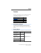
RS485 (DSI) Protocol C-3 Parameter Configuration The following PowerFlex 4M parameters are used to configure the drive to operate on a network. Parameter Details Reference P106 [Start Source] Set to 5 “RS485 (DSI) Port” if Start is controlled from the network. Page 3-9 P108 [Speed Reference] Set to 5 “RS485 (DSI) Port” if the Speed Reference is controlled from the network. Page 3-11 C302 [Comm Data Rate] Sets the data rate for the RS485 (DSI) Port.
C-4 RS485 (DSI) Protocol Writing (06) Logic Command Data The PowerFlex 4M drive can be controlled via the network by sending Function Code 06 writes to register address 8192 (Logic Command). P106 [Start Source] must be set to 5 “RS485 (DSI) Port” in order to accept the commands. In addition to being written, register address 8192 can be read using Function Code 03.
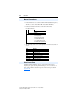
RS485 (DSI) Protocol C-5 Writing (06) Reference The Speed Reference to a PowerFlex 4M drive can be controlled via the network by sending Function Code 06 writes to register address 8193 (Reference). P108 [Speed Reference] must be set to 5 “RS485 (DSI) Port” in order to accept the Speed Reference. In addition to being written, register address 8193 can be read using Function Code 03. Reference Address (Decimal) 8193 Description A decimal value entered as xxx.x where the decimal point is fixed.
C-6 RS485 (DSI) Protocol Reading (03) Feedback The Feedback (Output Frequency) from the PowerFlex 4M drive can be read via the network by sending Function Code 03 reads to register address 8451 (Feedback). Feedback(1) Address (Decimal) 8451 (1) Description A xxx.x decimal value where the decimal point is fixed. For example, a decimal “123” equals 12.3 Hz and “300” equals 30.0 Hz. Returns the same data as Reading (03) Parameter d001 [Output Freq].
RS485 (DSI) Protocol C-7 Reading (03) and Writing (06) Drive Parameters To access drive parameters, the Modbus register address equals the parameter number. For example, a decimal “1” is used to address Parameter d001 [Output Freq] and decimal “39” is used to address Parameter P109 [Accel Time 1]. Additional Information Refer to http://www.ab.com/drives/ for additional information. PowerFlex 4M Adjustable Frequency Drive FRN 1.xx - 2.
C-8 RS485 (DSI) Protocol Notes: PowerFlex 4M Adjustable Frequency Drive FRN 1.xx - 2.
Appendix D RJ45 DSI Splitter Cable The PowerFlex 4M drive provides a RJ45 port to allow the connection of a single peripheral device. The RJ45 DSI Splitter Cable can be used to connect a second DSI peripheral device to the drive. Connectivity Guidelines ! ATTENTION: Risk of injury or equipment damage exists. The peripherals may not perform as intended if these Connectivity Guidelines are not followed. Precautions should be taken to follow these Connectivity Guidelines.
D-2 RJ45 DSI Splitter Cable DSI Cable Accessories PIN 1 S Slave Port M RJ45 Splitter Cable – Catalog Number: AK-U0-RJ45-SC1 Master Port PIN 8 RJ45 Two-Position Terminal Block Adapter – Catalog Number: AK-U0-RJ45-TB2P TB2 (PIN 5) PIN 8 TB1 (PIN 4) PIN 1 RJ45 Adapter with Integrated Termination Resistor – Catalog Number: AK-U0-RJ45-TR1 PIN 8 PIN 1 PowerFlex 4M Adjustable Frequency Drive FRN 1.xx - 2.
RJ45 DSI Splitter Cable D-3 Connecting an RS-485 Network DSI Drives AK-U0-RJ45-SC1 AK-U0-RJ45-TR1 Terminating Resistor (end of network) AK-U0-RJ45-TB2P Two-position Terminal Block or or Customer supplied RJ45 male-to-RJ45 male cables with wires connected at pins 4 and 5 only. Both the Master (M) and Slave (S) ports on the RJ45 Splitter Cable operate as standard RS-485 ports in this configuration. PowerFlex 4M Adjustable Frequency Drive FRN 1.xx - 2.
D-4 RJ45 DSI Splitter Cable Notes: PowerFlex 4M Adjustable Frequency Drive FRN 1.xx - 2.
Index A AC Supply Ground, 1-5 Source, 1-3 Ungrounded, 1-3 Advanced Program Group Parameters, 3-19 Ambient Temperatures, 1-2 Armored Cable, 1-10 Auto Rstrt Tries Fault, 4-4 Auxiliary Input Fault, 4-3 B Before Applying Power, 2-1, 2-2 C Drive Frame Size, P-2, B-6 Drive Grounding, 1-5 Drive Overload Fault, 4-4 Drive Ratings, P-4, A-1 DriveExecutive, 3-1 DriveExplorer, 3-1 E Earthing, see Grounding EMC/RFI Grounding, Filter, 1-6 Interference, 1-21 Enclosure Rating, Changing, 1-2 ESD, Static Discharge, P-3
Index-2 G General Precautions, P-3 Ground Fault, 4-3 Grounding Filter, 1-6 General, 1-5 H Heatsink OvrTmp Fault, 4-3 HW OverCurrent Fault, 4-3 I I/O Wiring, 1-13 Wiring Examples, 1-15, 1-18 I/O Board Fail Fault, 4-4 Input Contactor, 1-12 Input Fusing, 1-7 Input Potentiometer, 1-15 Input Power Conditioning, 1-4 Installation, 1-1 Integral Keypad, 2-3 Interference, EMC/RFI, 1-21 K Keypad, 2-3 L LEDs, 2-3 P Parameter Descriptions, 3-1 Types, 3-1 Viewing and Editing, 2-4 Parameter Checksum Fault, 4-4 Param
Index-3 Software, 3-1 Start and Speed Reference Selection and Control, 1-19, 1-20 Start/Stop, Repeated, 1-12 Start-Up Checklist, 2-1, 2-2 Static Discharge, ESD, P-3 Status LEDs, 2-3 Supply Source, AC, 1-3 SW OverCurrent Fault, 4-4 System Grounding, 1-5 T Terminal Block I/O, 1-13 Power, 1-12 Terminal Block Group Parameters, 3-13 Three Wire Control, 1-15, 1-18 Two Wire Control, 1-15, 1-18 U UnderVoltage Fault, 4-3 Ungrounded Supply, 1-3 Unshielded Power Cables, 1-9 W Watts Loss, A-5 Wiring, 1-1 Block Diagr
Index-4 Notes: PowerFlex 4M Adjustable Frequency Drive FRN 1.xx - 2.
www.rockwellautomation.com Power, Control and Information Solutions Headquarters Americas: Rockwell Automation, 1201 South Second Street, Milwaukee, WI 53204-2496 USA,Tel: (1) 414.382.2000, Fax: (1) 414.382.