Quick Start PowerFlex 520-Series Adjustable Frequency AC Drive PowerFlex 523 Catalog Number 25A PowerFlex 525 Catalog Number 25B This Quick Start guide summarizes the basic steps needed to install, start-up and program the PowerFlex 520-Series Adjustable Frequency AC Drive. The information provided DOES NOT replace the User Manual and is intended for qualified drive service personnel only.
PowerFlex 520-Series Adjustable Frequency AC Drive ATTENTION: • Before installing, configuring, operating or maintaining this product, read this document and the documents listed in the Additional Resources section for installing, configuring, or operating equipment. Users should familiarize themselves with installation and wiring instructions in addition to requirements of all applicable codes, laws, and standards.
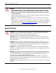
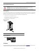
PowerFlex 520-Series Adjustable Frequency AC Drive Mounting Considerations • Mount the drive upright on a flat, vertical and level surface. Frame Screw Size Screw Torque A M5 (#10...24) 1.56...1.96 Nm (14...17 lb-in.) B M5 (#10...24) 1.56...1.96 Nm (14...17 lb-in.) C M5 (#10...24) 1.56...1.96 Nm (14...17 lb-in.) D M5 (#10...24) 2.45...2.94 Nm (22...26 lb-in.) E M8 (5/16 in.) 6.0...7.4 Nm (53...65 lb-in.) • Protect the cooling fan by avoiding dust or metallic particles.
PowerFlex 520-Series Adjustable Frequency AC Drive Ambient Operating Temperatures See Appendix B of the PowerFlex 520-Series User Manual, publication 520-UM001 for option kits.
PowerFlex 520-Series Adjustable Frequency AC Drive Ungrounded Distribution Systems ATTENTION: PowerFlex 520-Series drives contain protective MOVs that are referenced to ground. These devices must be disconnected if the drive is installed on an ungrounded or resistive grounded distribution system. ATTENTION: Removing MOVs in drives with an embedded filter will also disconnect the filter capacitor from earth ground.
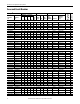
PowerFlex 520-Series Adjustable Frequency AC Drive Input Ratings PowerFlex PowerFlex Voltage 523 525 Range kVA HP kW HP kW 100...120V AC (-15%, +10%) – 1-Phase Input, 0...230V 3-Phase Output 25A-V1P6N104 – 0.25 0.2 0.25 0.2 1.6 85...132 0.8 25A-V2P5N104 25B-V2P5N104 0.5 0.4 0.5 0.4 2.5 85...132 1.3 25A-V4P8N104 25B-V4P8N104 1.0 0.75 1.0 0.75 4.8 85...132 2.5 25A-V6P0N104 25B-V6P0N104 1.5 1.1 1.5 1.1 6.0 85...132 3.2 200...240V AC (-15%, +10%) – 1-Phase Input, 0...230V 3-Phase Output 25A-A1P6N104 – 0.25 0.
Input Ratings PowerFlex PowerFlex Voltage 523 525 Range HP kW HP kW 25A-D013N114 25B-D013N114 7.5 5.5 7.5 5.5 13.0 323...528 25A-D017N114 25B-D017N114 10.0 7.5 10.0 7.5 17.0 323...528 25A-D024N114 25B-D024N114 15.0 11.0 15.0 11.0 24.0 323...528 25A-D030N114 25B-D030N114 20.0 15.0 15.0 11.0 30.0 323...528 25A-D037N114 25B-D037N114 25.0 18.5 20.0 15.0 37.0 323...528 25A-D043N114 25B-D043N114 30.0 22.0 25.0 18.5 43.0 323...528 525...600V AC (-15%, +10%) – 3-Phase Input, 0...
PowerFlex 520-Series Adjustable Frequency AC Drive Technical Specifications PowerFlex 523 Specifications Input/Output Ratings Output Frequency: 0...500 Hz (Programmable) Efficiency: 97.5% (Typical) Digital Control Inputs (Input Current = 6 mA) SNK (Sink) Mode: SRC (Source) Mode: 0...6V = ON 18...24V = ON 18...24V = OFF 0...6V = OFF Approvals TED 966X LIS UL ® IN TED 966X LIS UL508C C UL CSA 22.
PowerFlex 520-Series Adjustable Frequency AC Drive Power Wiring Recommended Shielded Wire Location Standard (Option 1) Rating/Type Description 600V, 90 °C (194 °F) XHHW2/RHW-2 • Four tinned copper conductors with XLPE insulation. Anixter B209500-B209507, Belden 29501-29507, or equivalent • Copper braid/aluminum foil combination shield and tinned copper drain wire. • PVC jacket. Standard (Option 2) Tray rated 600V, 90 °C (194 °F) • Three tinned copper conductors with XLPE insulation.
PowerFlex 520-Series Adjustable Frequency AC Drive I/O Wiring Recommended Signal Wire Signal Type/ Where Used Analog I/O & PTC Remote Pot Encoder/Pulse I/O Belden Wire Type (or equivalent)(1) Description Minimum Insulation Rating 2 (18 AWG), twisted pair, 100% shield with drain(2) 8760/9460 0.750 mm 8770 0.750 mm2 (18 AWG), 3 conductor, shielded 9728/9730 0.196 mm2 (24 AWG), individually shielded pairs 300V, 60 °C (140 °F) (1) Stranded or solid wire.
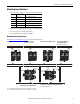
PowerFlex 520-Series Adjustable Frequency AC Drive Control Terminal Block PowerFlex 523 Control I/O Wiring Block Diagram (1) 01 02 03 SNK SRC 04 05 06 +24V Relay N.O. Relay Common Relay N.C. 11 R1 +10V R2 12 13 R3 14 15 C1 C2 Digital In DigIn TermBlk 05 Sel J8 SNK SRC R1 R2 R3 01 11 02 12 J7 Pulse In Typical SNK wiring Digital Common DigIn TermBlk 05/Pulse DigIn TermBlk 06 +24V DC +10V DC 0-10V Input Analog Common 4-20mA Input Pot must be 1...10 k ohm 2 W min.
PowerFlex 520-Series Adjustable Frequency AC Drive PowerFlex 523 Control I/O Terminal Designations No. R1 R2 R3 01 Signal Relay N.O. Relay Common Relay N.C. Stop Default Fault Fault Motor Running Coast Description Normally open contact for output relay. Common for output relay. Normally closed contact for output relay. Three wire stop. However, it functions as a stop under all input modes and cannot be disabled.
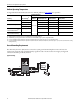
PowerFlex 520-Series Adjustable Frequency AC Drive PowerFlex 525 Control I/O Wiring Block Diagram Safety 1 Safety 2 Safety +24V 01 S1 Safe-Torque-Off 02 S2 03 S+ SNK SRC 04 05 06 07 08 +24V Relay 1 N.O. Relay 1 Common Relay 2 Common Relay 2 N.C.
PowerFlex 520-Series Adjustable Frequency AC Drive PowerFlex 525 Control I/O Terminal Designations No. R1 R2 R5 R6 01 02 Signal Relay 1 N.O. Relay 1 Common Relay 2 Common Relay 2 N.C. Stop DigIn TermBlk 02/ Start/Run FWD Default Fault Fault Motor Running Motor Running Coast Run FWD Description Normally open contact for output relay. Common for output relay. Common for output relay. Normally closed contact for output relay. Three wire stop.
PowerFlex 520-Series Adjustable Frequency AC Drive Prepare For Drive Start-Up ATTENTION: Power must be applied to the drive to perform the following start-up procedures. Some of the voltages present are at incoming line potential. To avoid electric shock hazard or damage to equipment, only qualified service personnel should perform the following procedure. Thoroughly read and understand the procedure before beginning. If an event does not occur while performing this procedure, Do Not Proceed.
PowerFlex 520-Series Adjustable Frequency AC Drive Start, Stop, Direction, and Speed Control Factory default parameter values allow the drive to be controlled from the keypad. No programming is required to start, stop, change direction, and control speed directly from the keypad. IMPORTANT To disable reverse operation, see A544 [Reverse Disable]. See Fault Codes on page 29 for an explanation of the fault codes.
PowerFlex 520-Series Adjustable Frequency AC Drive Viewing and Editing Parameters The following is an example of basic integral keypad and display functions. This example provides basic navigation instructions and illustrates how to program a parameter. Step 1 2 Key When power is applied, the last user-selected Basic Display Group parameter number is briefly displayed with flashing characters. The display then defaults to that parameter’s current value.
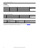
PowerFlex 520-Series Adjustable Frequency AC Drive Basic Display Group Parameters See the PowerFlex 520-Series Adjustable Frequency AC Drive User Manual, publication 520-UM001 for detailed descriptions of the parameters listed here, as well as the full list of available parameters. No. b001 b002 b003 b004 b005 b006 Parameter Min/Max [Output Freq] 0.00/[Maximum Freq] Output frequency present at T1, T2 & T3 (U, V & W). Does not include slip frequency. [Commanded Freq] 0.
PowerFlex 520-Series Adjustable Frequency AC Drive No. b022 b023 b024 b025 b026 b027 b028 b029 Parameter Min/Max [Elapsed MWh] 0.0/6553.5 MWh Accumulated output energy of the drive. [Energy Saved] 0.0/6553.5 kWh Total energy savings of using this drive compared to an across the line starter since the last reset of the meters. [Accum kWh Sav] 0.0/6553.5 kWh Total approximate accumulated energy savings of the drive compared to using an across the line starter. [Accum Cost Sav] 0.0/6553.
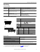
PowerFlex 520-Series Adjustable Frequency AC Drive Smart Start-Up with Basic Program Group Parameters The PowerFlex 520-series drive is designed so that start-up is simple and efficient. The Basic Program group contains the most commonly used parameters. See the PowerFlex 520-Series Adjustable Frequency AC Drive User Manual, publication 520-UM001 for detailed descriptions of the parameters listed here, as well as the full list of available parameters. = Stop drive before changing this parameter.
PowerFlex 520-Series Adjustable Frequency AC Drive = Stop drive before changing this parameter. = Parameter is specific to PowerFlex 525 drives only. No. Parameter P043 [Minimum Freq] Sets the lowest frequency the drive outputs. PF 525 Min/Max 0.00/500.00 Hz Display/Options 0.01 Hz Default 0.00 Hz 0.00/500.00 Hz 0.01 Hz 60.
PowerFlex 520-Series Adjustable Frequency AC Drive Advanced Program Group Parameters See the PowerFlex 520-Series Adjustable Frequency AC Drive User Manual, publication 520-UM001 for detailed descriptions of the parameters listed here, as well as the full list of available parameters. = Stop drive before changing this parameter. = Parameter is specific to PowerFlex 525 drives only. No. Parameter Min/Max A410... [Preset Freq x] 0.00/500.
PowerFlex 520-Series Adjustable Frequency AC Drive PF 525 No. A438 A439 A440 A441 PF 525 A442, A444, A446 A443, A445, A447 A448, A450 = Stop drive before changing this parameter. = Parameter is specific to PowerFlex 525 drives only. Parameter Min/Max [DB Threshold] 10.0/110.0% Sets the DC bus voltage threshold for Dynamic Brake operation. If DC bus voltage rises above this level, Dynamic Brake turns on.
PowerFlex 520-Series Adjustable Frequency AC Drive = Stop drive before changing this parameter. = Parameter is specific to PowerFlex 525 drives only. No. Parameter A458 [PID x Trim Sel] Sets the PID output as trim to the source reference.
PowerFlex 520-Series Adjustable Frequency AC Drive = Stop drive before changing this parameter. = Parameter is specific to PowerFlex 525 drives only. No. Parameter Min/Max A466 [PID x Preload] 0.0/500.0 Hz Sets the value used to preload the integral component on start or enable. A478 PF 525 Display/Options 0.1 Hz Default 0.0 Hz 0 = “Normal” 1 = “Inverted” 0 = “Normal” 0.01 0.00 0.01 0.00 1 400 0.1 A Drive Rated Amps x 1.1 (Normal Duty); Drive Rated Amps x 1.5 (Heavy Duty) 0.
PowerFlex 520-Series Adjustable Frequency AC Drive PF 525 No. A498 PF 525 A499 PF 525 A500 PF 525 A509 PF 525 A510, A512, A514 = Stop drive before changing this parameter. = Parameter is specific to PowerFlex 525 drives only. Parameter Min/Max [Motor Rr] 0.00/655.35 ohm Rotor resistance of induction motor. [Motor Lm] 0.0/6553.5 mH Mutual Inductance of induction motor. [Motor Lx] 0.0/6553.5 mH Leakage Inductance of induction motor.
PowerFlex 520-Series Adjustable Frequency AC Drive = Stop drive before changing this parameter. = Parameter is specific to PowerFlex 525 drives only. No. Parameter Min/Max A535 [Motor Fdbk Type] 0/5 Selects the encoder type. PF 525 ATTENTION: The loss of analog input, encoder or other feedback may cause unintended speed or motion. Take appropriate precautions to guard against possible unintended speed or motion.
PowerFlex 520-Series Adjustable Frequency AC Drive = Stop drive before changing this parameter. = Parameter is specific to PowerFlex 525 drives only. No. Parameter A551 [Fault Clear] Resets a fault and clears the fault queue. PF 525 A552 A553 Min/Max 0/2 [Program Lock] 0000/9999 Protects parameters against change by unauthorized personnel with a 4-digit password. [Program Lock Mod] 0/3 Determines the lock mode used in parameter A552 [Program Lock].
PowerFlex 520-Series Adjustable Frequency AC Drive PF 525 No. A566 PF 525 A567 A568 A569 A570 A571 A572 = Stop drive before changing this parameter. = Parameter is specific to PowerFlex 525 drives only. Parameter Min/Max [Pos Reg Gain] 0.0/200.0 Sets the gain adjustment for the position regulator. [Max Traverse] 0.00/300.00 Hz Sets the amplitude of triangle wave speed modulation. [Traverse Inc] 0.00/300.
PowerFlex 520-Series Adjustable Frequency AC Drive No.
PowerFlex 520-Series Adjustable Frequency AC Drive No. F109 F110 Fault Mismatch C-P Keypad Membrane F111(1) Safety Hardware F114 uC Failure F122 I/O Board Fail F125 F126 Flash Update Req NonRecoverablErr F127 DSIFlashUpdatReq Action Set P053 [Reset To Defalts] to 3 “Power Reset”. • Cycle power. • Replace control module if fault cannot be cleared. • Check safety input signals. If not using safety, verify and tighten jumper for I/O terminals S1, S2 and S+.
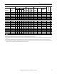
PowerFlex 520-Series Adjustable Frequency AC Drive Dimensions and Weight IP 20/Open Type – Dimensions are in mm and (in.). Weights are in kg and (lb). C A D Esc B Sel E Frame Size A B C D E A 72.0 (2.83) 87.0 (3.43) 109.0 (4.29) 130.0 (5.12) 185.0 (7.28) B 152.0 (5.98) 180.0 (7.09) 220.0 (8.66) 260.0 (10.24) 300.0 (11.81) C 172.0 (6.77) 172.0 (6.77) 184.0 (7.24) 212.0 (8.35) 279.0 (10.98) D 57.5 (2.26) 72.5 (2.85) 90.5 (3.56) 116.0 (4.57) 160.0 (6.30) E 140.0 (5.51) 168.0 (6.61) 207.0 (8.
PowerFlex 520-Series Adjustable Frequency AC Drive Network Communication PowerFlex 520-Series RS784 (DSI) Protocol This section contains only basic information to setup the PowerFlex 520-series RS485 (DSI) protocol connection with your PowerFlex 520-series drive. See the PowerFlex 520-Series Adjustable Frequency AC Drive User Manual, publication 520-UM001 for more information. PowerFlex 520-series drives support the RS485 (DSI) protocol to allow efficient operation with Rockwell Automation peripherals.
PowerFlex 520-Series Adjustable Frequency AC Drive The following PowerFlex 520-series drive parameters are used to configure the drive to operate on a DSI network. Configuring Parameters for DSI Network Parameter Description P046 [Start Source 1] Set to 3 “Serial/DSI” if Start is controlled from the network P047 [Speed Reference1] Set to 3 “Serial/DSI” if Speed Reference is controlled from the network. C123 [RS485 Data Rate] Sets the data rate for the RS485 (DSI) port.
PowerFlex 520-Series Adjustable Frequency AC Drive Drive and Adapter Status Indicators ➊ ➋ ENET LINK Item Name State Description ➊ Adapter is not connected to the network ENET EtherNet/IP ➋ LINK FWD ENET LINK EtherNet/IP ➌ ➌ Esc FAULT Off Steady Adapter is connected to the network and drive is controlled through Ethernet. Flashing Adapter is connected to the network but drive is not controlled through Ethernet. Off Adapter is not connected to the network.
Important Information Solid-state equipment has operational characteristics differing from those of electromechanical equipment. Safety Guidelines for the Application, Installation and Maintenance of Solid State Controls (publication SGI-1.1 available from your local Rockwell Automation sales office or online at http://www.rockwellautomation.com/literature/) describes some important differences between solid-state equipment and hard-wired electromechanical devices.