2705-DN42 DeviceNet Interface Communication Board Installation Instructions This document describes how to install a DeviceNet communications board.
Overview LED Indicator The RediSTATION has one bicolor LED (red/green) to show its operating status. The LED shows the following indications. Color State None Off Solid Red Flashing Solid Green Flashing Indication No power. Unrecoverable fault. Output error or configuration error. Normal runtime operation. The RediSTATION device is operating as a slave to the master controller. Device is idle or not allocated to a master. The LED is visible when the cover of the enclosure is removed.
DeviceNet Connection The RediSTATION receives all power and communications through the DeviceNet cable. A separate power supply is not required. This is the only external connection to the RediSTATION. The RediSTATION connects to the DeviceNet using the DeviceNet terminal block on the communication board.
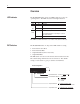
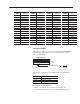
Installation and Mounting Setting the DIP Switches The setting of the DIP switch on the circuit board determines: • • • • DeviceNet node address DeviceNet data rate Output flash rate Output fault state The location of the DIP switch and the factory defaults are shown below. DIP Switches OFF = 0 ON = 1 10 9 8 7 6 5 4 3 2 1 Setting the DeviceNet Node Address DIP switches 1 to 6 set the node address (0 to 63) of the RediSTATION on the DeviceNet network. The address is set using binary addressing.
DeviceNet Address Switch Settings 6 1 DeviceNet Address Switch Settings 6 1 DeviceNet Address Switch Settings 6 1 DeviceNet Address Switch Settings 6 1 0 000000 16 010000 32 100000 48 110000 1 000001 17 010001 33 100001 49 110001 2 000010 18 010010 34 100010 50 110010 3 000011 19 010011 35 100011 51 110011 4 000100 20 010100 36 100100 52 110100 5 000101 21 010101 37 100101 53 110101 6 000110 22 010110 38 100110 54 110110 7 000111 23 01011
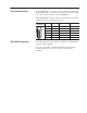
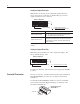
Setting the Output Fault State DIP switch 9 sets the state of the outputs (pilot lights) when the device detects an error. The factory default setting is to turn the outputs off when an error is detected. Default Configuration OFF = 0 ON = 1 10 9 8 7 6 5 4 3 2 1 Output Fault State 0 = Outputs Turn Off on Fault 1 = Outputs Hold Last State on Fault Output Fault States Description Outputs Retain Last State When communications is lost, the station stops sending signals.
Operations Modes of Operation The RediStation has 3 modes of operations: • Powerup / Reset mode • Run mode • Error mode Powerup/Reset Mode During a powerup or reset, the RediSTATION: 1. Clears outputs (turns outputs off) and sets the LED indicator to solid red. 2. Performs powerup diagnostic tests including: – – – – EPROM checksum test RAM read/write test Watchdog timer test Serial number verification If any test fails, the outputs remain off and the LED remains solid red.
If an output error is detected, the RediSTATION sets the appropriate message bits and remains in run mode. In run mode, you can configure the outputs to: • turn on • turn off • flash DIP switch 10 controls the rate of flashing for outputs. The RediSTATION also supports DeviceNet configuration messages that are received over the network. Error Mode In error mode (LED turns red), the RediSTATION monitors the error state for correct operation. Errors are critical or noncritical.
DeviceNet Operations The Allen-Bradley 1747-SDN and 1771-SDN DeviceNet Scanner Modules are master devices on the DeviceNet network. The RediSTATION supports the Master/Slave Connection Set for master/slave communications on the DeviceNet network.
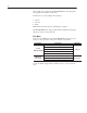
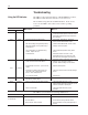
Troubleshooting Using the LED Indicator The LED provides status information on RediSTATION operations. The LED is visible when the enclosure cover is removed. The troubleshooting chart shows LED indications. It also shows how to use the LED to detect and correct common operating problems. LED Color None State Red Solid Red Green Flashing Solid Wh it Means: What s Wh to do: What 1. RediSTATION is not receiving input power. 1.
User-Defined Configuration An unpopulated configuration is available for customer configuration and installation of operator devices.
Specifications of DeviceNet Interface Board Electrical Supply Voltage 11 to 25 VDC Power Consumption 7 Watts Maximum Inputs Maximum Number Type Voltage/Current Isolation 4 Hard Contact Sourcing 24 VDC/24mA Maximum None Outputs Maximum Number Voltage/Current Isolation 2 24 VDC/100mA Maximum None Communications DeviceNet Baud Rates Distance Max.
Connecting Devices This section shows how to connect devices to the DeviceNet Interface Board and connect the DeviceNet cable to the DeviceNet terminal block connector. To install devices: 1. Connect the device terminals to the I/O connector using the I/O cables. An I/O cable consists of a twisted (red/black) wire pair. Each set of contacts or pilot light connects to an I/O cable.
To simplify wiring, input devices and output devices attach to opposite ends of the I/O connector. The following table defines pin functions on the I/O connector. Output devices connect to pins 1–2 and 3–4. Input devices connect to pins 5–6, 7–8, 9–10 and 11–12. Unused pins are left open.
41061-116-01(A) Copyright 1999 Allen-Bradley Company, Inc.