
User Manual


14
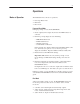
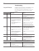
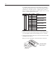
To simplify wiring, input devices and output devices attach to
opposite ends of the I/O connector. The following table defines
pin functions on the I/O connector. Output devices connect to
pins 1–2 and 3–4. Input devices connect to pins 5–6, 7–8, 9–10
and 11–12. Unused pins are left open.
I/O Connector Pin # Pin Label Function
1 OUT1+
Conne s O e i e
2 OUT1–
Conne
ct
s
O
utput D
e
v
i
c
e
3 OUT2+
Conne s O e i e
4 OUT2–
Conne
ct
s
O
utput D
e
v
i
c
e
5 IN4+
Conne s n e i e
6 IN4–
Conne
ct
s
I
n
put D
e
v
i
c
e
7 IN3+
Conne s n e i e
8 IN3–
Conne
ct
s
I
n
put D
e
v
i
c
e
9 IN2+
Conne s n e i e
10 IN2–
Conne
ct
s
I
n
put D
e
v
i
c
e
11 IN1+
Conne s n e i e
12 IN1–
Conne
ct
s
I
n
put D
e
v
i
c
e
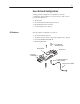
2. Mount the circuit board using the spacers and mounting screws
provided. Tighten circuit board mounting screws to 14 in-lbs.
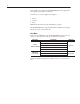
3. Attach the 6 DeviceNet cable leads to the DeviceNet removable
terminal block connector.
Page 3 provides a description of the DeviceNet connections.
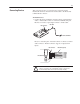
Removable Terminal
Block Connector
Common
CAN Low
Shield
CAN High
VDC+
E GND
Pin 1
Pin 6