Allen-Bradley Dataliner DL5 Slave Displays (Cat. No.
Important User Information Because of the variety of uses for the products described in this publication, those responsible for the application and use of this control equipment must satisfy themselves that all necessary steps have been taken to assure that each application and use meets all performance and safety requirements, including any applicable laws, regulations, codes and standards.
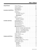
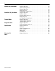
Table of Contents Using this Manual Introduction to the DL5 Slave Installation and Startup Configuring the DL5 Slave Chapter Objectives . . . . . . . . . . . . . . . . . . . . . . . . . . . . . . . . . . . . Overview of this Manual . . . . . . . . . . . . . . . . . . . . . . . . . . . . . . . Intended Audience . . . . . . . . . . . . . . . . . . . . . . . . . . . . . . . . . . . . Conventions Used. . . . . . . . . . . . . . . . . . . . . . . . . . . . . . . . . . . . . Related Publications . . . . . . .
ii Dataliner (DL) Slave Mode PanelView (PV) Slave Mode Terminal Mode Diagnostic Mode Specifications Character Set Index Publication 2706-6.4 Chapter Objectives . . . . . . . . . . . . . . . . . . . . . . . . . . . . . . . . . . . . Slave Mode Operation . . . . . . . . . . . . . . . . . . . . . . . . . . . . . . . . . Example Messages . . . . . . . . . . . . . . . . . . . . . . . . . . . . . . . . . . . . Display Options. . . . . . . . . . . . . . . . . . . . . . . . . . . . . . . . . . . . . . .
Preface Using this Manual Chapter Objectives Overview of this Manual Read this chapter to familiarize yourself with the rest of the Dataliner DL5 Slave Message Display manual. You will learn about: • contents of this manual • intended audience • conventions used • related publications This manual describes how to install and use your DL5 Slave display.
P-2 Using this Manual Intended Audience Conventions Used Related Publications No specialized knowledge is required to configure and install the DL5 slave display. However, we assume the following: • The person responsible for equipment connections is familiar with standard wiring practices and electrical codes in your area. • Communication cabling is done by a person having an understanding of basic communications terminology and cabling.
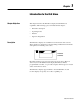
Chapter 1 Introduction to the DL5 Slave Chapter Objectives Description This chapter describes the DL5 Slave display and summarizes its capabilities. The following topics are included in this chapter: • DL5 Slave description • Operating modes • Features • Typical configurations The DL5 Slave displays are available in one-line and two-line versions. These displays are designed for panel mounting in industrial environments and require a 12-24V DC power source.
1-2 Introduction to the DL5 Slave Operating Modes The DL5 Slave has four operating modes: • DL Slave • PV Slave • Terminal • Diagnostic DL (Dataliner) Slave Mode Use this mode when connecting one or more DL5 slaves to a DL40 Plus master display, PLC or SLC controller. A DL5 Slave may be connected to a DL40 Plus using an RS-232 link (single drop only). Multiple DL5 slave displays may be connected to an RS-485 link using an RS-485 to RS-232 converter such as the Black Box LD-485A-MP.
Introduction to the DL5 Slave Features 1-3 DL5 Slave displays have these features: 14 Segment Matrix Characters One or Two-Line Vacuum Fluorescent Display Operate (up) Operates on standard 12-24V DC 1 2 SW1 DIP Switch (Operate/Configure) Position 2 Not Used 1 Configure (down) 2 SW1 RS-232 Port Publication 2706-6.
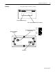
1-4 Introduction to the DL5 Slave Typical Configurations Here are some of the most typical applications: DL40 Plus to DL5 Slave DL5 Slave SYSTEM CHECK NORMAL DL40 Plus (Master) Note: You can use either the RS-232 or the RS-485 port.
Chapter 2 Installation and Startup Chapter Objectives Mounting the DL5 Slave This chapter describes how to mount and make electrical connections to the DL5 Slave display. The following topics are described: • Mounting Instructions • Panel Cutout Dimensions • Power Connections • Powerup Sequence The following pages provide panel cutout dimensions and overall dimensions for the DL5 Slave displays. You can also mount the DL5 Slaves in a custom panel or enclosure.
2-2 Installation and Startup Panel Cutout Dimensions All dimensions are in inches (millimeters) 5.75 (146.1) 5.38 (136.7) 2.25 (57.2) Full Size Cutout Template 1.12 (28.6) 1.31 (33.3) 2.88 (73.2) 0.171 (4.3) Diameter, 4-places DL5 Mounting Dimensions All dimensions are in inches (millimeters) 3.12 (79.3) Front 6.25 (158.8) 5.25 (133.4) Top 4.31 (108.0) Max Depending on Panel Thickness 0.22 (5.6) Max Panel Publication 2706-6.
Installation and Startup Electrical Precautions 2-3 Install the DL5 Slave display conforming to NFPA 70E, Electrical Safety Requirements for Employee Workplaces. In addition to the NFPA general guidelines, refer to the following: Careful cable routing helps minimize electrical noise. Route incoming power to the module by a separate path from the communication cables.
2-4 Installation and Startup Hazardous Location Installations ! ! ! RS-232 Connections ATTENTION: THIS EQUIPMENT IS SUITABLE FOR USE IN CLASS I, DIVISION 2, GROUPS A, B, C AND D, OR NON-HAZARDOUS LOCATIONS ONLY. ATTENTION: EXPLOSION HAZARD SUBSTITUTION OF COMPONENTS MAY IMPAIR SUITABILITY FOR CLASS 1, DIVISION 2. ATTENTION: EXPLOSION HAZARD - DO NOT CONNECT OR DISCONNECT EQUIPMENT UNLESS POWER HAS BEEN SWITCHED OFF OR THE AREA IS KNOWN TO BE NON-HAZARDOUS.
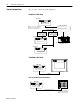
Installation and Startup 2-5 DL5 Slave to DL40 Plus Master RS-232 Port Connect a single DL5 slave to a DL40 Plus master as shown below. You can also use the DTAM Plus programming cable (Catalog No. 2707-NC2) with a male-female pin adapter. DL40 Plus Master TXD RXD Signal Ground DL5 Slave 2 TXD 3 RXD 5 Signal Ground 2 3 5 DL5 Slave to PanelView RS-232 Printer Port Connect the DL5 Slave to a PanelView RS-232 printer port as shown below.
2-6 Installation and Startup DL5 Slave to 1771-DB BASIC Module BASIC Module RS-232 Peripheral Port Shield TXD RXD Signal Ground RTS CTS DSR DTR 1 2 3 7 4 5 6 20 DL5 Slave RS-232 Port 2 TXD (RS-232 Out) 3 RXD (RS-232 In) 5 Signal Ground DL5 Slave to 1746-BAS BASIC Module BASIC Module RS-232 PRT1 Port Shield RXD TXD COM DTR CTS DSR DTR Publication 2706-6.
Installation and Startup 2-7 DL5 Slave to PLC-5 Channel 0 Connect the DL5 Slave to a PLC-5 Channel 0 port as shown below. You can also use programming cable (Catalog No. 2706-NC12). PLC-5 Channel 0 25 Pin D Shell Connector DCD 8 RXD 3 TXD 2 DTR 20 Common 7 DSR 6 RTS 4 CTS 5 Chassis Ground 1 DL5 Slave RS-232 Port Shield 1 2 3 4 5 6 7 8 9 No Connection TXD RXD No Connection Signal Common DSR RTS CTS No Connection DL5 Slave to SLC Channel 0 Connect the DL5 Slave to an SLC Channel 0 port as shown below.
2-8 Installation and Startup Power Connections Before making power connections, make sure that the power is turned off. The DL5 Slave requires 12-24Volts DC, 250-125 mA (300mA inrush). TB2 1 Common ! Operate / Configure Switch 2 12-24V DC ATTENTION: Improper wiring of the power connections may result in damage to the DL5 Slave. The DL5 Slave does not contain any fuses. We recommend that you use external fusing to prevent damage to the DL5 slave or power supply.
Installation and Startup Startup Sequence 2-9 When power is applied to the DL5 Slave a powerup sequence of displays are shown. The first display on powerup is the sign-on banner identifying the hardware and firmware: DL5 SLAVE 2L V1.00 04/02/99 Following the sign-on banner, all of the display pixels are turned on for 2 seconds followed by a series of informational messages indicating the current DIP switch settings. Each display lasts for about four seconds.
2-10 Installation and Startup Publication 2706-6.
Chapter 3 Configuring the DL5 Slave Chapter Objectives This chapter describes how to configure the DL5 display using an ASCII programming terminal or personal computer running a terminal emulation program such as HyperTerminal (Windows 95 or 98). Configuring a DL5 Slave You can configure a DL5 Slave with: • an ASCII (dumb) terminal connected to the DL5 Slave RS-232 port • a personal computer connected to the DL5 Slave RS-232 port and running a terminal emulation program.
3-2 Configuring the DL5 Slave Using Terminal Emulation If you don’t have an ASCII programming terminal, you can use your computer with a terminal emulation program such as HyperTerminal. The following example shows HyperTerminal, other terminal programs will be similar. 5. Locate the HyperTerminal or other program on your computer. Often the terminal emulation programs can be found on the Start>Accessories menu. 6. Setup the terminal emulation program.
Configuring the DL5 Slave Configuring a DL5 Slave Message Display 3-3 1. Connect the DL5 Slave to a communication port on your computer or programming terminal. Use cable (Catalog No. 2706-NC13) for standard 9-pin connections or cable (catalog No. 2706-NC12) for 25-pin connections. Page 3-1 lists the available programming cables for other configurations. 2.
3-4 Configuring the DL5 Slave DL5 Configuration Menu Start of Menu MODE= DL SLAVE [Enter] [Space Bar] MODE= PV SLAVE [Enter] [Space Bar] MODE= TERMINAL BAUD= 9600 [Enter] Press [SpaceBar] to scroll through baud rates [Space Bar] MODE= DIAGNOSTIC [Enter] BAUD= 9600 Press [SpaceBar] to scroll through baud rates Enter 3-digit address and press [Enter] [Enter] BAUD= 9600 [Space Bar] ADDRESS= XXX ENABLE CURSOR? Y Press [SpaceBar] to scroll through baud rates Press [Y] or [N] then press [Enter]
Configuring the DL5 Slave DL5 Configuration Options 3-5 The following items can be selected or entered from the configuration menu: Run Mode Use the [SpaceBar] to select from the following run modes: • • • • DL Slave Mode PV Slave Mode Terminal Mode Diagnostic Mode Serial Address Enter a 3-digit address from 000 to 127 (013 & 018 are invalid). The address is entered as a decimal value. The serial address only applies to the DL Slave mode.
3-6 Configuring the DL5 Slave Publication 2706-6.
Chapter 4 Dataliner (DL) Slave Mode Chapter Objectives Slave Mode Operation This chapter describes the operation of the DL5 Slave in DL Slave Mode and contains the following topics: • Slave mode description • Slave mode protocol • Example messages • Display options • Clearing one or more lines DL Slave Mode is selected through the configuration menu as described in Chapter 3.
4-2 Dataliner (DL) Slave Mode Address The address of the slave display that will receive the message. This is a single byte character from 1 to 127 decimal (01 through 7F hex). Note: Do not use 13 (0Dhex) or 18 (12hex) as an address. These are reserved and the DL5 automatically converts these addresses to 127 (7F hex). Address 127 is a global address that accepts all messages regardless of the address. In addition, any message sent with an address of 127 is sent to all slave displays.
Dataliner (DL) Slave Mode Display Options 4-3 Use the following control codes in the message text for flash and reset functions. Any other control codes are ignored. [Ctrl][F] Control-F (06 hex) is the flash code. Send this code when you want all the characters on the line to flash. The [Ctrl][F] code can appear anywhere in the text portion of the message. You can turn flash on and off multiple times in a message. At the start of each new line of message text, the flash option is turned off.
4-4 Dataliner (DL) Slave Mode Publication 2706-6.
Chapter 5 PanelView (PV) Slave Mode Chapter Objectives This chapter describes the operation of the DL5 Slave in the PV Mode. The following topics are described: • PV Slave Mode description • PV Mode protocol • Display options PV Slave Mode Use the PanelView (PV) Slave Mode to send the DL5 Slave messages from a PanelView operator terminal. The DL5 Slave acts like a printer attached to the PanelView communication port. Any messages printed by the PanelView are displayed on the DL5 Slave.
5-2 PanelView (PV) Slave Mode Display Options Use the following control codes to control the appearance of messages displayed in PV Mode. [Ctrl][F] (06 hex) Flash command. Send the [Ctrl][F] command when you want the display characters to flash. Following the first flash code, all the characters on the display will flash. If a second [Ctrl][F] is received, the display stops flashing. At the start of each new line of message text, the flash option is turned off. [Ctrl][J] (0A hex) Line Feed command.
PanelView (PV) Slave Mode Line Display Characteristics 5-3 The PanelView Slave mode has two special display characteristics that make messages easier to read: Line to Line Delay After each individual line is displayed, there is a one second pause before the next line is displayed. This delay provides time for each line to be read. Cursor Movement Command Delay Line wrap, carriage return, line feed and form feed operations are not executed immediately.
5-4 PanelView (PV) Slave Mode Publication 2706-6.
Chapter 6 Terminal Mode Chapter Objectives Terminal Mode Operation This chapter describes the operation of the DL5 Slave in Terminal Mode and contains the following topics: • Terminal mode operation • Protocol Terminal mode allows more control over messages than the basic Slave Mode setting.
6-2 Terminal Mode Terminal Mode Protocol Message text and control codes are sent serially to the DL5 Slave in terminal mode. The following control codes are used: Cursor Up (Ctrl-K ) (0B hex) Positions the cursor directly above the current cursor position. If the cursor is on the first line, the cursor is moved to the last line on the display. On one line displays, the cursor does not move. Cursor Down (Ctrl-V) (16 hex) Positions the cursor directly below the current cursor position.
Terminal Mode 6-3 Delete Line (Esc and then R) (1B, 52 hex) Clears the current line. The cursor remains at its current position. Insert Line (Esc and then E) (1B, 45 hex) Moves the current line and all lines below it down one line (text on bottom line is lost). Then clears the current line. The cursor remains at its current position. Set Cursor Position (Esc,=,,) (1B, 3D hex) Moves the cursor to the specified row and column. Refer to the following table.
6-4 Terminal Mode Publication 2706-6.
Chapter 7 Diagnostic Mode Chapter Objectives This chapter describes the operation of the DL5 Slave in the Diagnostic Mode. Use the diagnostic mode to verify communications with a host device. Diagnostic mode displays the exact data being sent by a host device. Use the diagnostic mode as a temporary installation and troubleshooting aid. Set the DL5 Slave for diagnostic mode as described in Chapter 3.
7-2 Diagnostic Mode Publication 2706-6.
Appendix A Specifications Display Characters Character Height One line display Two line display 5.31 mm (0.209 inch) 5.94 mm (0.234 inch) Character Set Alphanumeric Upper Case Only Characters per Display Line 16 Viewing Distance - Approximate 3 meters (10 feet) Character Type Vacuum fluorescent, 14 segment characters. Filtered to blue/green color.
A-2 Specifications Certifications Listings UL listed for UL-508 Industrial Control Equipment Class I, Groups A, B, C, and D Division 2, Hazardous Locations Listed for Canadian Safety Standards Class 1, Division 2, Groups A, B, C, D Hazardous Location Publication 2706-6.
Appendix B Character Set Publication 2706-6.
B-2 Character Set Publication 2706-6.
Index A address serial 3-5 contents overview P-1 conventions P-2 applications PanelView to DL5 slave 1-4 PLC, PC, other device to DL5 slave 1-4 cursor enable 3-5 audience P-2 D B baud rate 3-5 C cables configuration 3-1 carriage return DL slave mode 4-2 PanelView slave mode 5-2 characters display 1-3 clear lines 4-3 communications baud rate 3-5 data errors 7-1 specifications A-1 configuration communication settings 3-2, 3-3 menu 3-4 configurations typical 1-3 configure/operate switch 1-3, 2-8 configu
I-ii Index F features DL5 slave 1-2 flash code 4-3, 5-2 form feed PanelView slave mode 5-2 H hazardous locations installing 2-4 humidity A-1 I installation cutouts 2-2 electrical precautions 2-3 hazardous locations 2-4 L line feed 5-2 line number DL slave mode 4-2 lines clearing 4-3 M O offline programming software 3-1 operate/configure switch 1-3, 2-8 operating mode 1-2 operating modes 1-2 P panel cutout dimensions 2-2 PanelView slave mode carriage return 5-2 cursor movement delay 5-3 display opti
Index I-iii T temperature operating ranges A-1 terminal mode 1-2 clear screen 6-2 cursor down 6-2 cursor home 6-2 cursor left 6-2 cursor return 6-2 cursor right 6-2 cursor up 6-2 de-energize relay 6-3 delete line 6-3 display status 6-3 flashing mode 6-3 insert line 6-3 line feed 6-2 new line 6-2 reverse line feed 6-2 set cursor invisible 6-3 set cursor position 6-3 set cursor visible 6-3 terminal emulation 3-2 U UL listing A-1 V vibration A-1 voltage input requirements 2-3 Publication 2706-6.
I-iv Index Publication 2706-6.
Back Cover Publication 2706-6.4 - August, 1999 41061-126-01(A) © (1999) Rockwell International Corporation. Printed in the U.S.A.