InView Communications 2706-PRIO, 2706-PDH485, 2706-PDHP, 2706-PDNET, 2706-PCNET, 2706-PENET, 2706-PENET1 User Manual
Important User Information Solid state equipment has operational characteristics differing from those of electromechanical equipment. Safety Guidelines for the Application, Installation and Maintenance of Solid State Controls (publication SGI-1.1 available from your local Rockwell Automation sales office or online at http://literature.rockwellautomation.com) describes some important differences between solid state equipment and hard-wired electromechanical devices.
Summary of Changes This document describes the InView Communication Module. Revision bars in the margin identify updated information. Changes for this version of the document include: Change Added a note that communication modules should be configured serially before it is mounted to the display 1-5 Added that the communication utility creates files with the extension of .ivc which is different from InView message files which have the extension of .
2 Summary of Changes Publication 2706-UM017C-EN-P - March 2006
Table of Contents Chapter 1 Introduction to InView Connectivity Controller Based Communications . . . . . . . . . . . . . . . . . . . PC Based Communications . . . . . . . . . . . . . . . . . . . . . . . . Set the 2706-PENET1 IP Address . . . . . . . . . . . . . . . . . . . . Create a New InView Network Communication Application 1-2 1-3 1-5 1-7 Chapter 2 Install InView Communication Modules Mount Module to 2706-P42, 2706-P43 and 2706-P44 Displays . . . . . . . . . . . . . . . . . . . . . . . . . . . . .
ii Table of Contents Appendix A InView Communication Module Specifications Communication Specifications . . . . . . . . . . . . . . . . . . . . . . A-1 Power Supply Requirements . . . . . . . . . . . . . . . . . . . . . . .
Chapter 1 Introduction to InView Connectivity InView message displays come standard with RS-232 and RS-485 communications for quick and easy integration. For applications requiring industrial or commercial networks, InView communications modules can be used to integrate your display into new and existing networks.
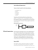
1-2 Introduction to InView Connectivity Controller Based Communications InView controller based communication can be used to trigger messages and update variables on an InView display. InView communication allows for connection into new and existing control environments. Point-to-point RS-232 Serial Communications Point-to-point serial communications allow the use of a controller to trigger messages and update variables on an InView display.
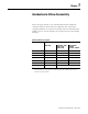
Introduction to InView Connectivity 1-3 Industrial Network Communications InView communication modules allow InView displays to communicate with controllers over the following networks. • • • • • • Data Highway Plus DH-485 Remote I/O DeviceNet ControlNet Ethernet The InView communication modules take controller based communications one step farther. They allow InView message displays to communicate on the core Allen Bradley networks.
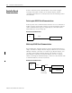
1-4 Introduction to InView Connectivity your existing office network to communicate information to the entire factory. See publication 2706-IN008, for information on installing and setting up Ethernet TCP/IP. EtherNet TCP/IP PC TCP/IP Module 2706-PENET1 InView Display Serial RS-232 Communications PC based RS-232 connection to communicate to an InView display. This is done via the InView messaging software, Instant Messenger, or the ActiveX control in RSView32 software.
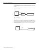
Introduction to InView Connectivity 1-5 Serial RS-485 Communications PC based RS-485 serial networks. For multi-drop connection to an InView display, an AIC+ (RS-232 to RS-485 converter) or a 2706-P9 type InView display can be used off the PC comm port. This allows individual control of multiple displays on a single network up to 1219 m (4000 ft).
1-6 Introduction to InView Connectivity 4. Navigate to the Communications tab. 5. Assure Ethernet TCP/IP is selected under the Download Protocol. 6. Click the Configure Communications button to set the IP Address. The Ethernet TCP/IP Communications Configuration dialog opens. 7. Enter IP Address desired, the MAC Address and click Setup. • MAC ID is case sensitive • The PC being used to set the IP should be on the same subnet and should be in the same range of IP addresses as the 2706-PENET1.
Introduction to InView Connectivity Create a New InView Network Communication Application 1-7 The communication utility allows the InView message display to be configured to communicate with an Allen-Bradley controller over an industrial network. The communication utility creates a file of extension .ivc, which you can save, reuse, or edit. This is separate from InView message files, which is of extension .ivp. All communication and tag parameters are configured from a common dialog.
1-8 Introduction to InView Connectivity 6. Click the configure communications button in the Industrial Networks Communications section on the bottom of the communications tab. The following dialog appears. 7. Select a communication protocol or click the Open Saved Project button to open a previously saved .ivc configuration file. Either dialog appears. or A saved InView Network Communications file (*.ivc) can still be edited within the utility and either downloaded to the communication module or saved.
Introduction to InView Connectivity 1-9 8. If creating a new InView network communications file, select a protocol from the list. Then, choose an InView serial communication rate. This is the communication rate that the communication module and the InView display communicate at. Currently all InView displays communicate at 9600 bps, with the exception of the 2706-P92 and 2706-P94 displays. Those can communicate at either 9600 bps or 19200 bps. 9.
1-10 Introduction to InView Connectivity Publication 2706-UM017C-EN-P - March 2006
Chapter 2 Install InView Communication Modules Mount Module to 2706-P42, 2706-P43 and 2706-P44 Displays The InView communication module is designed to mount to the track of the InView 2706-P42, 2706-P43 and 2706-P44 displays. 1. Align the tabs on the back plate of the module to the track on the display. 2. Tighten mounting screws until they bottom out against the back plate.
2-2 Install InView Communication Modules To wire the communication module to the InView display: 1. Disconnect power to InView display. ATTENTION Hazardous voltage. Contact with high voltage may cause death or serious injury. Always disconnect power to the InView display prior to servicing. 2. Remove six screws on the power supply cover (on 2706-P4x). 2706-P42, 2706-P43, 2706-P44 3. Route the serial cable through the cable grip (shipped with module). 4.
Install InView Communication Modules TIP TB1 Incoming serial wires TIP 2-3 Be sure to place the wires so they are not caught by screws when replacing the power supply cover, and also so they do not interfere with fan operation. TB1 Black (GND)1 Red (PWR, +5V)2 Orange (TX)3 Brown (RX)4 5 6 7 8 The 2706-P_M communication modules are powered through the serial cable by the display (Series C). 8. Tighten the cable grip cap until the cable is securely fastened. 9.
2-4 Install InView Communication Modules 2. Open the front of the InView case by turning the latches counter clockwise and carefully lower the front of the case. 3. Install the Communication Kit (2706-P_K) to the mounting plate located near TB1 using the supplied standoffs and screws. 4. Torque the screws to 0.68 Nm (6 in-lbs).
Install InView Communication Modules 2-5 4. Mount the cable grip to the InView display housing. 5. Tighten the locknut finger-tight and rotate an additional 1/2 turn. 6. Tighten the cable grip cap until the cable is securely fastened. 7. Carefully close the InView case and tighten the latches by turning them clockwise. 8. Connect the InView to a power source. Use Communication Module with a 2706-P22R Display The 2706-P22R InView panel mount display can be used with a 2706-P_P communication module.
2-6 Install InView Communication Modules RS-232 1 2 6 3 7 4 8 5 9 24V dc (Customer Supplied) To Controller (Customer Supplied Cable) DIN Rail 24V dc 2706-NC13 Serial Cable (Supplied) RS-232 1 2 6 Network Port 3 7 4 8 5 9 Class 2 24V dc 5. Connect the communications module to the 2706-P22R display by using the supplied serial cable. 6. Provide 24 volts ±25 percent, 1A DC to the communications module.
Chapter 3 InView Communication Module Connections Chapter Objectives This chapter describes network and device connections for InView communication modules.
3-2 InView Communication Module Connections Cable Tables Refer to the following tables for a summary of InView communication module connections to controllers and network interface modules. Runtime Communication Cables - To Processors InView to SLC SLC-5/03, 5/04, 5/05 CH0 (9-pin RS-232) (DF1 or DH-485) SLC 5/03 CH1 (RJ45) (DH-485) SLC 5/04 CH1 (DH+) SLC 5/05 CH1 (ENET) DH-485 Communication Port (RJ45) 1747-C10 (2m/6ft) 1747-C11 (0.
InView Communication Module Connections 3-3 InView to PLC-5, ControlLogix, MicroLogix1000, MicroLogix 1200, and MicroLogix 1500LSP Protocol InView Communication Module Standard Comm Port PLC-5, PLC-5C, PLC-5E CH0 (25-pin RS-232) (DF1) ControlLogix CH0 (9-pin RS-232) (DF1) MicroLogix 1000, 1200, 1500LSP CH0 (8-pin Mini DIN) (DF1 or DH-485) EtherNet/IP Ethernet Communication Port to PLC-5E with Ethernet cable Use 1756-ENET Module with Ethernet cable Use 1761-NET-ENI Module with Ethernet cable Remot
3-4 InView Communication Module Connections Runtime Communication Cables - to Network Interface Module InView to 1747-AIC, 1761-NET-AIC, 1761-NET-DNI, and 1761-NET-ENI Protocol InView Communication Module Standard Comm Port 1747-AIC 1761-NET-AIC DH-485 DH-485 Communication Port (RJ45) 1747-C10 N/A (2m/6ft) 1747-C11 (0.
InView Communication Module Connections 3-5 Remote I/O Terminal Ports The Remote I/O versions of the InView communication module has a remote I/O port and an RS-232 port. Use the remote I/O port to: • communicate with the remote I/O scanner port on a PLC controller. • communicate with SLC controllers using a 1747-SN remote I/O scanner module. • communicate with other remote I/O scanners.
3-6 InView Communication Module Connections Supported RIO Connections Controller Scanner Comments ControlLogix 1756-DHRIO Connect InView communication modules through the 1756-DHRIO module. PLC-5/11, 5/15(1), 5/20, 5/25, 5/30, 5/60, 5/80, 5/250 PLC Integral 1771-SN Connect InView communication modules directly to the remote I/O port (scanner mode). Connect InView communication modules through the 1771-SN subscanner module.
InView Communication Module Connections 3-7 Make Remote I/O Connections To connect an InView communication module to a remote I/O scanner, use cable Catalog No. 1770-CD (equivalent to Belden 9463). The maximum cable length (link distance) is determined by the communication rate. • 2,800 m (10,000 ft) for 57.6 Kbps • 1,400 m (5,000 ft) for 115.2 Kbps • 700 m (2,500 ft) for 230.4 Kbps See Programmable Controller Wiring and Grounding Guidelines, publication 1770-4.1.
3-8 InView Communication Module Connections DH+ Connections This section describes connections for the DH+ InView communication modules including: • DH+ ports. • typical DH+ system configuration. • making DH+ connections. DH+ Ports The DH+ versions of the InView communication modules have a DH+ port and an RS-232 port. Use the DH+ port to: • communicate with a PLC-5 controller on the Allen-Bradley DH+ link via the processor’s DH+ port.
InView Communication Module Connections 3-9 Typical DH+ System Configuration For more information on the Allen-Bradley DH+ link, refer to: • Enhanced PLC-5 Programmable Controllers Installation Instructions, publication 1785-5.7. • Data Highway/Data Highway Plus/Data Highway II/Data Highway 485 Cable Installation Manual, publication 1770-6.2.2.
3-10 InView Communication Module Connections Make DH+ Connections Use the Belden 9463 twin axial cable (1770-CD) to connect a DH+ InView communication module to the DH+ link. You can connect a DH+ link in 2 ways. • Trunk line/drop line - from the drop line to the connector screw terminals on the DH+ connectors of the processor. • Daisy chain - to the connector screw terminals on the DH+ connectors on the processor. Follow these guidelines when installing DH+ communication links.
InView Communication Module Connections DH-485 Terminal Connections 3-11 This section describes connections for the DH-485 InView communication modules. • • • • DH-485 communication module ports Connecting to a single SLC controller (Point-to-Point) Connecting to a DH-485 network Connecting a computer DH-485 Ports (RJ45) DH-485 InView communication modules have two DH-485 ports and an RS-232 port.
3-12 InView Communication Module Connections Connect to a Single SLC Controller (Point-to-Point) To connect a DH-485 InView communication module to a single SLC controller use one of these cables. • 0.3 m (1 ft) catalog no. 1747-C11 • 1.83 m (6 ft) catalog no. 1747-C10 • 6.1 m (20 ft) catalog no. 1747-C20 InView to SLC Controller Connections SLC Controller SLC 500 Communications Connector InView DH-485 Communications Port Pin 1 Cable, Catalog No. 1747-C10 Cable, Catalog No. 1747-C11 Cable, Catalog No.
InView Communication Module Connections 3-13 Connect to a DH-485 Network This section shows how to connect an InView DH-485 communication module to multiple SLC controllers on a DH-485 network through the AIC link coupler. DH-485 Connections Link Coupler Catalog No. 1747-AIC Power Source or 1747-NP1 SLC Processor Cable Catalog No. 1747-C10 Catalog No. 1747-C11 Catalog No.
3-14 InView Communication Module Connections The illustration below shows how to connect an InView DH-485 communication module to a MicroLogix or SLC controller using the AIC+ link coupler (Catalog No. 1761-NET-AIC). InView Display Connected to MicroLogix or SLC with an AIC+ 2706-P22R, 2706-P4x, 2706-P7x,2706-P9x AIC+ 1761-NET-AIC InView display RS-232 Port 77156-094 DH-485 Comm Module InView display MicroLogix 1000, 1200, 1500LSP Cable Cat. No. 1761-CBL-AS03 Cat. No. 1761-CBL-AS09 Cat. No.
InView Communication Module Connections 3-15 Connect a Computer On InView DH-485 communication modules, applications are transferred: • through the DH-485 programming connector to the InView communication module. • through any node on a DH-485 network. To connect a computer to the InView communication module, you need: • a cable (same cables used to transfer applications from APS software to SLC) – 0.3 m (1 ft) cable, catalog no. 1747-C11 – 1.83 m (6 ft) cable, catalog no. 1747-C10 – 6.
3-16 InView Communication Module Connections Connecting a Computer to DH-485 Connector Using a Power Supply InView Messaging Wallmount Power Supply Cat. No. 1747-NP1 DH-485 Comm Module To DH-485 Programming Connector 25-pin to 9-pin Adapter (if required) Personal Computer Interface Converter (Cat. No. 1747-PIC) To DH-485 Communications Port Cable Cat. No. 1747-C10 Cat. No. 1747-C11 Cat. No.
InView Communication Module Connections ControlNet Connections 3-17 This section describes connections for the ControlNet InView communication modules including: • • • • • ControlNet Protocol. compatible ControlNet Controllers. ControlNet ports on the InView communication module. typical ControlNet network. making ControlNet connections. Related Information For more information on ControlNet products, refer to the following publications. • ControlNet System Overview, publication 1786-2.
3-18 InView Communication Module Connections Compatible ControlNet Controllers The ControlNet InView communication module communicates with a PLC-5C (using PCCC commands) or a ControlLogix processor (using CIP protocol) using unscheduled messaging. The following controllers are supported. • ControlLogix using 1756-CNB module • PLC-5/20C, -5/40C, -5/60C, -5/80C processors ControlNet Ports ControlNet versions of the InView communication module have a ControlNet communication port and an RS-232 serial port.
InView Communication Module Connections 3-19 Typical ControlNet Network Below is a typical ControlNet network with a InView communication module installed on a network drop.
3-20 InView Communication Module Connections Make ControlNet Connections Use the pinout information below to connect the InView communication module to a ControlNet network. IMPORTANT Follow the ControlNet network layout and design as specified in the ControlNet Cable System Planning and Installation Manual, publication 1786-6.2.
InView Communication Module Connections 3-21 NAP and Redundant Cables Refer to the ControlNet Cable System Planning and Installation manual, publication 1786-6.2.1, for descriptions of cables, taps, and connectors. For information on purchasing these items, refer to the Allen-Bradley ControlNet Cable System Component List, Publication AG-2.2. ControlNet Cables, Taps, and Connectors Item Cat. No.
3-22 InView Communication Module Connections • Use the RS-232 port to connect an InView display to trigger messages. For details on connecting to the RS-232 port, see the last section in this chapter. InView Communication Module DeviceNet Ports InView DeviceNet Communication Module 1 2 6 3 7 4 8 5 9 RS-232 Port DeviceNet Port Make DeviceNet Connections Use one of the cables below to connect the DeviceNet version of the InView communication module to a DeviceNet network.
InView Communication Module Connections 3-23 Typical DeviceNet Network Below is a typical DeviceNet network with InView communication modules installed on 2 of the network drops. A DeviceNet network requires a 24V dc power supply. DeviceNet power consumption is 24 mA to 90 mA at 24V dc. The InView communication module does not receive its power from the network. DeviceNet Network PLC-5 Controller SLC 5/04 Controller or DeviceNet Scanner Module (Cat. No. 1747-SDN) DeviceNet Scanner Module (Cat. No.
3-24 InView Communication Module Connections EtherNet/IP Connections The EtherNet/IP InView communication module can communicate on an EtherNet TCP/IP network with the following devices.
InView Communication Module Connections 3-25 Ethernet Connector The Ethernet connector is an RJ45, 10/100Base-T connector. The pinout for the connector is shown below.
3-26 InView Communication Module Connections Typical EtherNet/IP Configuration The following illustration shows a ControlLogix controller (with 1756-ENET/B modules), a PLC-5E controller, SLC 5/05, a MicroLogix/CompactLogix/FlexLogix (with 1761-NET-ENI module), and an Ethernet InView communication module connected to an EtherNet/IP network. Note that each node has a unique IP address.
InView Communication Module Connections 3-27 Computer Connection Computer To RS-232 Port of InView Communications Module Available Cables Cat. No. 2711-NC13, 5 m (16.4 ft) Cat. No. 2711-NC14, 10 m (32.7 ft) Cat. No.
3-28 InView Communication Module Connections Publication 2706-UM017C-EN-P - March 2006
Chapter 4 Application Guide New techniques and application notes using InView displays are continually being added and updated. Please refer to these web pages for new or updated information. • http://www.ab.com/eoi/inview/ • http://support.rockwellautomation.com/ ControlNet Communication and Tag Setup Screens The InView message display communicates with PLC processors, FlexLogix controllers, or ControlLogix 5000 controllers on a ControlNet network using Unscheduled Messaging.
4-2 Application Guide InView Parameters • Node address. Node address (1 to 99 decimal) of the InView display on the ControlNet network. • Interscan Delay. Time interval (in ms) between display updates. The range is 100 to 1,000 ms. The default is 100. This parameter determines how frequently the InView display requests unscheduled data. Network Node Parameters • Node Type. The type of controller that the InView display communicates with. • Node Address.
Application Guide 4-3 • Message Trigger Address. The controller address that triggers a message to display. This toggles between 0 and 1 in the controller. • Message Data Address. The starting address of the message data displayed. The message data contains the trigger command that the InView display recognizes (^T[message number]^M). • Message Array Size. The size of the array (16 to 128 characters for ControlNet) containing the message data.
4-4 Application Guide ControlLogix 5000 Controller ControlNet Communications Setup InView Parameters • Node address. Node address (1 to 99 decimal) of the InView display on the ControlNet network. • Interscan Delay. Time interval (in ms) between display updates. The range is 100 to 1,000 ms. The default is 100. This parameter determines how frequently the InView display requests Unscheduled data. Network Node Parameters • Node Type. The type of controller that the InView display communicates with.
Application Guide 4-5 For a Logix controller, a valid address consists of the ControlNet module’s node number (1 to 99) followed by a space, a Logix backplane number (usually 1) followed by a space, and a Logix slot number. Example: 99 1 99 IMPORTANT All four tags for Message Trigger Address, Message Data Address, Variable Trigger Address, Variable Data Address, and the array sizes must be entered and established in the controller as valid tags even if they are not used.
4-6 Application Guide • Variable Trigger Address. The controller address that triggers a message variable to display. This toggles between 0 and 1 in the controller. • Variable Data Address. The starting address of the variable data displayed. The variable data contains the update variable command that the InView display recognizes (^V[variable data]\[variable number]^M). • Variable Array Size. The size of the array (16 to 128 characters for ControlNet) containing the variable data.
Application Guide 4-7 SLC Controller DeviceNet Communications Setup InView Parameters • Node Address. Unique address (0 to 63) of the InView display on the DeviceNet network. You can select 64 to use the most recent address stored on the communications card. If you select 64, the node address is set from the network using a DeviceNet network configuration tool. • Baud Rate. Communication rate of the DeviceNet network. The options are AutoBaud, 125 Kbps, 250 Kbps, 500 Kbps, and PGM.
4-8 Application Guide I/O Scanner Parameters • Output Size. The number of words (0 to 64) received by the InView display from the scanner with each I/O message. The default is 0, which means no output I/O data is exchanged with the scanner. The output size must match the configuration in the master device. A minimum of 19 words is needed because the Message and Variable Data array sizes minimum are 16 bytes each plus 1 word each for the trigger. • Bus-off Interrupt.
Application Guide 4-9 • Message Data Address. The starting address of the message data displayed. The message data contains the trigger command that the InView display recognizes (^T[message number]^M). • Message Array Size. The size of the array (16 to 128 characters for DeviceNet) containing the message data. The maximum array size is dependent on the controller and must be an even integer. • Message Data Swap Bytes.
4-10 Application Guide PLC Processor DeviceNet Communication Setup InView Parameters • Node Address. Unique address (0 to 63) of the InView display on the DeviceNet network. You can also select 64 to use the most recent address stored on the communications card. If you select 64, the node address can be set from the network using a DeviceNet network configuration tool. • Baud Rate. Communication rate of the DeviceNet network. The options are AutoBaud, 125 Kbps, 250 Kbps, 500 Kbps, PGM.
Application Guide 4-11 I/O Scanner Parameters • Output Size. The number of words (0 to 64) received by the InView display from the scanner with each I/O message. The default is 0, which means no output I/O data is exchanged with the scanner. The output size must match the configuration in the master device. A minimum of 19 words is needed because the Message and Variable Data array sizes minimums are 16 bytes each plus 1 word each for the trigger. • Bus-off Interrupt.
4-12 Application Guide • Message Data Address. The starting address of the message data displayed. The message data contains the trigger command that the InView display recognizes (^T[message number]^M). • Message Array Size. The size of the array (16 to 128 characters for DeviceNet) containing the message data. The maximum array size is dependent on the controller and must be an even integer. • Message Data Swap Bytes.
Application Guide 4-13 ControlLogix Controller DeviceNet Communications Setup InView Parameters • Node Address. Unique address (0 to 63) of the InView display on the DeviceNet network. You can also select 64 to use the most recent address stored on the communications card. If you select 64, the node address can be set from the network using a DeviceNet network configuration tool. • Baud Rate. Communication rate of the DeviceNet network. The options are AutoBaud, 125 Kbps, 250 Kbps, 500 Kbps, PGM.
4-14 Application Guide I/O Scanner Parameters • Output Size. The number of words (0 to 64) received by the InView display from the scanner with each I/O message. The default is 0, which means no output I/O data is exchanged with the scanner. The output size must match the configuration in the master device. A minimum of 19 words is needed because the Message and Variable Data array sizes minimum are 16 bytes each plus 1 word each for the trigger. • Bus-off Interrupt.
Application Guide 4-15 • Message Data Address. The starting address of the message data displayed. The message data contains the trigger command that the InView display recognizes (^T[message number]^M). • Message Array Size. The size of the array (16 to 128 characters for DeviceNet) containing the message data. The maximum array size is dependent on the controller and must be an even integer. • Message Data Swap Byte.
4-16 Application Guide Data Highway Plus (DH+) Communication and Tag Setup Screens The InView message display communicates with PLC-5 controllers or SLC 5/04 controllers, ControlLogix 5000 controllers, or SoftLogix controllers on a DH+ network. PLC-5 Controller DH+ Communications Setup InView Parameters • Node address. Node address (0 to 77 octal) of the InView display on the DH+ network. • Baud Rate. The communication rate (57.6 Kbps, 115.2 Kbps, 230.4 Kbps) of the DH+ network.
Application Guide 4-17 • Node Address. The node address (0 to 77 octal) of the controller on the DH+ network. IMPORTANT All four tags for Message Trigger Address, Message Data Address, Variable Trigger Address, Variable Data Address, and the array sizes must be entered and established in the controller as valid tags even if they are not used. DH+ Tag Setup • Message Trigger Address. The controller address that triggers a message to display. This toggles between 0 and 1 in the controller.
4-18 Application Guide • Variable Array Size: The size of the array (16 to 80 characters for DHP) containing the variable data. The maximum array size is dependent on the controller and must be an even integer. The address tags are either an Integer (N) or ASCII (A) data file. Both the Message Trigger and Message Data addresses must fall entirely within a single 80 byte block, including the Message Data array size.
Application Guide 4-19 InView Parameters • Node address. Node address (0 to 77 octal) of the InView display on the DH+ network. • Baud Rate. The communication rate (57.6 Kbps, 115.2 Kbps, 230.4 Kbps) of the DH+ network. Network Node Parameters • Node Type. The type of controller that the InView display communicates with. • Node Address. The node address (0 to 77 octal) of the controller on the DH+ network.
4-20 Application Guide • Message Data Address. The starting address of the message data displayed. The message data contains the trigger command that the InView display recognizes (^T[message number]^M). • Message Array Size. The size of the array (16 to 80 characters for DHP) containing the message data. The maximum array size is dependent on the controller and must be an even integer. • Variable Trigger Address. The controller address that triggers a message variable to display.
Application Guide 4-21 ControlLogix 5000 Controller DH+ Communication Setup InView Parameters • Node address. Node address (0 to 77 octal) of the InView display on the DH+ network. • Baud Rate. The communication rate (57.6 Kbps, 115.2 Kbps, 230.4 Kbps) of the DH+ network. IMPORTANT Not all communication rates are supported by all 1756-DHRIO modules. Network Node Parameters • Node Type. The type of controller that the InView display communicates with. • Node Address.
4-22 Application Guide IMPORTANT All four tags for Message Trigger Address, Message Data Address, Variable Trigger Address, Variable Data Address, and the array sizes must be entered and established in the controller as valid tags even if they are not used. DH+ Tag Setup • Message Trigger Address. The controller address that triggers a message to display. This toggles between 0 and 1 in the controller. • Message Data Address. The starting address of the message data displayed.
Application Guide 4-23 • Variable Array Size. The size of the array (16 to 80 characters for DHP) containing the variable data. The maximum array size is dependent on the controller and must be an even integer. The address tags are an Integer (N) data file. Both the Message Trigger and Message Data addresses must fall entirely within a single 80 byte block, including the Message Data array size. You can choose to use any Integer data file, but you cannot use more than one data file.
4-24 Application Guide DH485 Communication Setup SLC Controller InView Parameters • Node address. Node address (0 to 31 decimal) of the InView display on the DH485 network. • Maximum address. Address of the highest node on the network. The default is 31. A low maximum address improves network performance. • Baud Rate. The communication rate (1.2 Kbps, 2.4 Kbps, 9.6 Kbps, 19.2 Kbps) of the DH485 network. The default is 19.2 Kbps. Network Node Parameters • Node Type.
Application Guide IMPORTANT 4-25 All four tags for Message Trigger Address, Message Data Address, Variable Trigger Address, Variable Data Address, and the array sizes must be entered and established in the controller as valid tags even if they are not used. DH485 Tag Setup • Message Trigger Address. The controller address that triggers a message to display. This toggles between 0 and 1 in the controller. • Message Data Address. The starting address of the message data displayed.
4-26 Application Guide • Variable Array Size. The size of the array (16 to 80 characters for DH485) containing the variable data. The maximum array size is dependent on the controller and must be an even integer. The address tags are either an Integer (N) or ASCII (A) data file. Both the Message Trigger and Message Data addresses must fall entirely within a single 80 byte block, including the Message Data array size.
Application Guide 4-27 InView Parameters • Node address. Node address (0 to 31 decimal) of the InView Display on the DH485 network. • Maximum address. Address of the highest node on the network. The default is 31. A low maximum address improves network performance. • Baud Rate. The communication rate (1.2 Kbps, 2.4 Kbps, 9.6 Kbps, 19.2 Kbps) of the DH485 network. The default is 19.2 Kbps. Network Node Parameters • Node Type. The type of controller that the InView display communicates with.
4-28 Application Guide • Message Trigger Address. The controller address that triggers a message to display. This toggles between 0 and 1 in the controller. • Message Data Address. The starting address of the message data displayed. The message data contains the trigger command that the InView display recognizes (^T[message number]^M ). • Message Array Size. The size of the array (16 to 80 characters for DH485) containing the message data.
Application Guide 4-29 SLC 5/05 Controller EtherNet/IP Communication Setup InView Parameters • InterScan Delay. Time interval (in milliseconds) between the InView display delays before re-reading data from the logic controller. The range is 100 to 1,000 ms. The default is 100 ms. Network Node Parameters • Node Type. The type of controller that the InView display communicates with. • Node Address.
4-30 Application Guide • Node Path. A 256-character string identifying the path to the end node. EtherNet/IP Configuration EtherNet Configuration • DHCP/BootP Enable. If you select this check box, the InView display is automatically assigned an IP address, Subnet Mask, and Gateway Address. These fields become read-only if the check box is selected. Clear the check box to manually assign an IP Address, Subnet Mask and Gateway Address. • IP Address.
Application Guide 4-31 • Gateway Address. A unique IP address of the Gateway connecting two individual IP networks into a system of networks. When a node needs to communicate with another network, the Gateway transfers the data between the two networks. This parameter interprets IP addresses when the network is divided into multiple networks. The first field cannot be 0 if any other fields contain a 0. This address can be left blank. DNS Parameters • DNS Enable.
4-32 Application Guide EtherNet/IP Tag Setup • Message Trigger Address. The controller address that triggers a message to display. This toggles between 0 and 1 in the controller. • Message Data Address. The starting address of the message data displayed. The message data contains the trigger command that the InView display recognizes (^T[message number]^M ). • Message Array Size. The size of the array (16 to 80 characters for SLC 5/05 controller) containing the message data.
Application Guide 4-33 • Variable Array Size. The size of the array (16 to 80 characters for SLC 5/05 controller) containing the variable data. The maximum array size is dependent on the controller and must be an even integer. The address tags are either an Integer ( N ) or ASCII ( A ) data file. Both the Message Trigger and Message Data addresses must fall entirely within a single 80 byte block, including the Message Data array size.
4-34 Application Guide InView Parameters • InterScan Delay. Time interval (in milliseconds) between the InView display delays before re-reading data from the logic controller. The range is 100 to 1,000 ms. The default is 100 ms. Network Node Parameters • Node Type. The type of controller that the InView display communicates with. • Node Address. The IP address or host name of the controller on the EtherNet/IP network that the InView display communicates.
Application Guide 4-35 EtherNet Configuration • DHCP/BootP Enable. If you select this check box, the InView Display is automatically assigned an IP address, Subnet Mask, and Gateway Address. These fields become read-only if the check box is selected. Clear the check box to manually assign an IP Address, Subnet Mask and Gateway Address. • IP Address. A unique IP address of the InView display node on the network. The default value is 0.0.0.0. • Subnet Mask.
4-36 Application Guide IMPORTANT All four tags for Message Trigger Address, Message Data Address, Variable Trigger Address, Variable Data Address, and the array sizes must be entered and established in the controller as valid tags even if they are not used. EtherNet/IP Tag Setup • Message Trigger Address. The controller address that triggers a message to display. This toggles between 0 and 1 in the controller. • Message Data Address. The starting address of the message data displayed.
Application Guide 4-37 • Variable Array Size. The size of the array (16 to 230 characters for PLC-5E controller) containing the variable data. The maximum array size is dependent on the controller and must be an even integer. The address tags are either an Integer ( N ) or ASCII ( A ) data file. Both the Message Trigger and Message Data addresses must fall entirely within a single 230 byte block, including the Message Data array size.
4-38 Application Guide InView Parameters • InterScan Delay. Time interval (in milliseconds) between the InView display delays before re-reading data from the logic controller. The range is 100 to 1,000 ms. The default is 100 ms. Network Node Parameters • Node Type. The type of controller that the InView display communicates with. • Node Address. The IP address or host name of the controller on the EtherNet/IP network that the InView display communicates.
Application Guide 4-39 EtherNet Configuration • DHCP/BootP Enable. If you select this check box, the InView display is automatically assigned an IP address, Subnet Mask, and Gateway Address. These fields become read-only if the check box is selected. Clear the check box to manually assign an IP Address, Subnet Mask and Gateway Address. • IP Address. A unique IP address of the InView display node on the network. The default value is 0.0.0.0. • Subnet Mask.
4-40 Application Guide IMPORTANT All four tags for Message Trigger Address, Message Data Address, Variable Trigger Address, Variable Data Address, and the array sizes must be entered and established in the controller as valid tags even if they are not used. EtherNet I/P Tag Setup • Message Trigger Address. The controller address that triggers a message to display. This toggles between 0 and 1 in the controller. • Message Data Address. The starting address of the message data displayed.
Application Guide 4-41 • Variable Array Size. The size of the array (16 to 254 characters for a ControlLogix controller) containing the variable data. The maximum array size is dependent on the controller and must be an even integer. The address tags are a SINT data type, however they can be named anything provided it follows this syntax: Name[element number]. Both the Message Trigger and Message Data addresses must fall entirely within a single 254 byte block, including the Message Data array size.
4-42 Application Guide PLC-5 Controller Remote I/O Communication Setup PLC/Scanner Parameters • Node Type. The type of controller that the InView display communicates with. InView Parameters • Rack. The unique address (0 to 76 octal) of the InView display on the Remote I/O link. The options are limited to the rack addresses supported by the type of controller selected under PLC/Scanner. • Baud Rate. The communication rate used on the Remote I/O link. The options are 57.6 Kbps (3,048 m (10,000 ft) max.
Application Guide IMPORTANT 4-43 All four tags for Message Trigger Address, Message Data Address, Variable Trigger Address, Variable Data Address, and the array sizes must be entered and established in the controller as valid tags even if they are not used. Remote I/O Tag Setup • Message Trigger Address. The controller address that triggers a message to display. This toggles between 0 and 1 in the controller. • Message Data Address. The starting address of the message data displayed.
4-44 Application Guide • Variable Array Size. The size of the array (16 to 128 characters for RIO) containing the variable data. The maximum array size is dependent on the controller and must be an even integer. The address tags are either an Integer (N) or ASCII (A) data file. Both the Message Trigger and Message Data addresses must fall entirely within its designated block transfer, including the Message Data array size.
Application Guide 4-45 SLC Controller with 1747-SN/B Scanner Remote I/O Communication Setup PLC Processor/Scanner Parameters • Node Type. The type of controller that the InView display communicates with. InView Parameters • Rack. The unique address (0 to 76 octal) of the InView display on the remote I/O link. The options are limited to the rack addresses supported by the type of controller selected under PLC/Scanner. • Baud Rate. The communication rate used on the remote I/O link. The options are 57.
4-46 Application Guide • Enable Pass-through. Enables or disables Pass-through for application transfers between a computer on the DH+ network and a PanelView terminal on the remote I/O network. IMPORTANT All four tags for Message Trigger Address, Message Data Address, Variable Trigger Address, Variable Data Address, and the array sizes must be entered and established in the controller as valid tags even if they are not used. Remote I/O Tag Setup • Message Trigger Address.
Application Guide 4-47 • Variable Data Address. The starting address of the variable data displayed. The variable data contains the update variable command that the InView display recognizes (^V[variable data]\[variable number]^M). • Variable Array Size. The size of the array (16 to 128 characters for RIO) containing the variable data. The maximum array size is dependent on the controller and must be an even integer. The address tags are either an Integer (N) or ASCII (A) data file.
4-48 Application Guide ControlLogix 5000 Controller Remote I/O Communication Setup PLC/Scanner Parameters • Node Type. The type of controller that the InView display communicates with. InView Parameters • Rack. The unique address (0 to 76 octal) of the InView display on the remote I/O link. The options are limited to the rack addresses supported by the type of controller selected under PLC/Scanner. • Baud Rate. The communication rate used on the remote I/O link. The options are 57.
Application Guide 4-49 • Enable Pass-through. Enables or disables Pass-through for application transfers between a computer on the DH+ network and a PanelView terminal on the remote I/O network. IMPORTANT All four tags for Message Trigger Address, Message Data Address, Variable Trigger Address, Variable Data Address, and the array sizes must be entered and established in the controller as valid tags even if they are not used. Remote I/O Tag Setup • Message Trigger Address.
4-50 Application Guide • Variable Array Size. The size of the array (16 to 128 characters for RIO) containing the variable data. The maximum array size is dependent on the controller and must be an even integer. The address tags are an Integer (N) data file. Both the Message Trigger and Message Data addresses must fall entirely within its designated block transfer, including the Message Data array size. IMPORTANT Variable Trigger and Variable Data addresses work the same as Variable Array Size.
Application Guide 4-51 1. Click the Save button to save your configuration as an InView Network Communications file (.ivc) for later loading or copying to another machine. 2. Click the Download button to download the configuration to the InView display that is connected to your computer using serial or network communications. 3. Select a Transfer Type and then OK to proceed with the download.
4-52 Application Guide If the computer in which the software is loaded on does not have RSLinx software, then the only Transfer Type available is the Internal COM ports. The communication rate for DF1 download must be 19200 bps. The DH485 communication module requires you to download the application over the DH485 network. You cannot download over the RS232 port on a DH485 communication module.
Chapter 5 InView Communication Module Troubleshooting Chapter Objectives This chapter tells you how to isolate and correct common operating problems. • Equipment required • Use troubleshooting chart • LED indicators Equipment Required Other than verifying that the correct power source is connected to the terminal (use a voltmeter), no electronic diagnostic equipment is required for troubleshooting.
5-2 InView Communication Module Troubleshooting Troubleshooting Table Problem Board does not power up. Probable Cause(s) 1. Improper connection to power source. Corrective Action(s) 1. Verify wiring and connections to power source. 2. Incorrect input voltage level. 3. DC power wires reversed. 2. Verify correct voltage is present at power terminals. 3. Make sure DC power positive and negative are connected to the proper terminals. Application file will not download (first download). 1.
InView Communication Module Troubleshooting 5-3 Troubleshooting Table Problem No communications with MicroLogix, ControlLogix, SLC or PLC controller. Probable Cause(s) 1. Communications (COMM) fault. 2. Communication rates not set properly. Corrective Action(s) 1. Check status of COMM LED. Verify cable connections using cable diagrams in Chapter 3. 3. Controller is not in run mode. 4. InView communication module board node and maximum node numbers are not set correctly. 2.
5-4 InView Communication Module Troubleshooting Indicators On InView communication modules, use the COMM and Fault LED indicators to isolate operating problems. The illustration below shows the location of these indicators. Communication Module Indicators COMM LED (LED 2) Fault LED (LED 1) DF1, DH-485, DH+ LED Indications LED This Pattern: Indicates: Comm(1) Solid Fill Normal operating state (no communication faults). No Fill Fault detected.
InView Communication Module Troubleshooting 5-5 Remote I/O LED Indications LED This pattern: Indicates: Comm(1) Solid Fill Normal operating state (no communication faults) No Fill Communications not functioning • Verify that communication rate and rack settings match the PLC processor settings • Verify proper InView communication module board to controller connections • Verify that the PLC processor enables Remote I/O communications Fault (1) Blinking No communications established.
5-6 InView Communication Module Troubleshooting Publication 2706-UM017C-EN-P - March 2006
Appendix A InView Communication Module Specifications Communication Specifications Attribute Value Operating Temperature (Inside Panel) 0…55 °C (32…131 °F) Storage Temperature -25…70 °C (-13…158 °F) Humidity (Operating and Non-Condensing) 5 … 95% Power Supply Requirements Shock 15 g Maximum Pulse Operating 30 g Maximum Pulse Non-Operating Vibration - Channel Mount 10 Hz < f < 57 Hz 0.012 in. p-p displacement 57 Hz < f 500 Hz 1.0g Vibration - DIN Rail Mount 10 Hz < f < 57 Hz 0.012 in.
A-2 InView Communication Module Specifications Publication 2706-UM017C-EN-P - March 2006
Index A DH+ communications application guide 4-1 C cables application file upload/download direct 3-4 DeviceNet 3-22 DH+ 3-10 DH-485 3-12 Ethernet 3-25 Remote I/O 3-7 runtime communication cables to network interface module 3-4 runtime communication cables to processor 3-2 Comm LED 5-4 communication specifications A-1 communications 1-2 Ethernet TCP/IP 1-3 industrial network 1-3 multi-drop RS-485 serial 1-2 PC Based 1-3 point-to-point RS-232 serial 1-2 serial RS-232 1-4 serial RS-485 1-5 controller base
2 Index L LED indicators Comm 5-4 Fault 5-4 link coupler 3-13, 3-14 M mount to P42, P43, P44 2-1 P72, P74, P92, P94 2-3 supported controllers 3-5 tag setup screens 4-41 RS-232 (DH-485) cables 3-26 connect a computer 3-26 connect a printer 3-26 RS-232 (DH-485) communications connect a computer 3-26 connect a printer 3-26 RS-232 serial port port pinout 3-26 S P PC based communications 1-3 PIC converter 3-15 power supply 3-15 requirements A-1 printer port setup port pinout 3-26 save or download applicat
Rockwell Automation Support Rockwell Automation provides technical information on the Web to assist you in using its products. At http://support.rockwellautomation.com, you can find technical manuals, a knowledge base of FAQs, technical and application notes, sample code and links to software service packs, and a MySupport feature that you can customize to make the best use of these tools.