
User Manual Manual

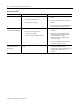
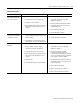
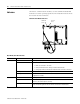
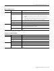

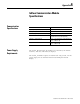

Table Of Contents
- 2706-UM017C-EN-P InView Communications User Manual
- Summary of Changes
- Table of Contents
- 1 - Introduction to InView Connectivity
- 2 - Install InView Communication Modules
- Mount Module to 2706-P42, 2706-P43 and 2706-P44 Displays
- Wire Communication Module to InView Display 2706-P42, 2706-P43, 2706-P44
- Mount Communication Kit to 2706-P72, 2706-P74, 2706-P92 and 2706-P94 Displays
- Wire Communication Kit to 2706-P72, 2706-P74, 2706-P92 and 2706-P94 Displays
- Use Communication Module with a 2706-P22R Display
- 3 - InView Communication Module Connections
- 4 - Application Guide
- ControlNet Communication and Tag Setup Screens
- DeviceNet Communication and Tag Setup Screens
- Data Highway Plus (DH+) Communication and Tag Setup Screens
- DH485 Communication and Tag Setup Screens
- EtherNet Communication and Tag Setup Screens
- RIO Communication and Tag Setup Screens
- Save or Download an Application File
- 5 - InView Communication Module Troubleshooting
- A - InView Communication Module Specifications
- Index
- Back Cover
1 Publication 2706-UM017C-EN-P - March 2006
Chapter
5
InView Communication Module
Troubleshooting
Chapter Objectives
This chapter tells you how to isolate and correct common operating
problems.
• Equipment required
• Use troubleshooting chart
• LED indicators
Equipment Required
Other than verifying that the correct power source is connected to the
terminal (use a voltmeter), no electronic diagnostic equipment is
required for troubleshooting.
Use the Troubleshooting
Table
The following pages provide a troubleshooting table for the
communication module board. This table lists the most common
operating problems, causes, and steps to correct them
WARNING
EXPLOSION HAZARD
Do not connect or disconnect equipment unless
power has been switched off and area is known to
be non-hazardous.