
User Manual Manual

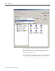
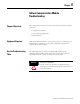
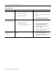
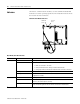
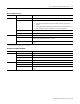

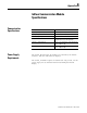

Table Of Contents
- 2706-UM017C-EN-P InView Communications User Manual
- Summary of Changes
- Table of Contents
- 1 - Introduction to InView Connectivity
- 2 - Install InView Communication Modules
- Mount Module to 2706-P42, 2706-P43 and 2706-P44 Displays
- Wire Communication Module to InView Display 2706-P42, 2706-P43, 2706-P44
- Mount Communication Kit to 2706-P72, 2706-P74, 2706-P92 and 2706-P94 Displays
- Wire Communication Kit to 2706-P72, 2706-P74, 2706-P92 and 2706-P94 Displays
- Use Communication Module with a 2706-P22R Display
- 3 - InView Communication Module Connections
- 4 - Application Guide
- ControlNet Communication and Tag Setup Screens
- DeviceNet Communication and Tag Setup Screens
- Data Highway Plus (DH+) Communication and Tag Setup Screens
- DH485 Communication and Tag Setup Screens
- EtherNet Communication and Tag Setup Screens
- RIO Communication and Tag Setup Screens
- Save or Download an Application File
- 5 - InView Communication Module Troubleshooting
- A - InView Communication Module Specifications
- Index
- Back Cover
Publication 2706-UM017C-EN-P - March 2006
InView Communication Module Troubleshooting 5-5
Remote I/O LED Indications
LED This pattern: Indicates:
Comm
(1)
Solid Fill Normal operating state (no communication faults)
No Fill Communications not functioning
• Verify that communication rate and rack settings match the PLC processor
settings
• Verify proper InView communication module board to controller connections
• Verify that the PLC processor enables Remote I/O communications
Blinking No communications established. PLC processor is in program mode.
Flashing When power is first applied (momentarily)
Fault No Fill Normal operating state
Solid Fill Fault detected. Cycle power to the terminal. If the fault still exists, the InView
communication module board requires servicing.
Blinking Hardware is functioning but no application is loaded or the current application is
corrupt.
(1)
Comm LED stays on until powerup self-test are complete
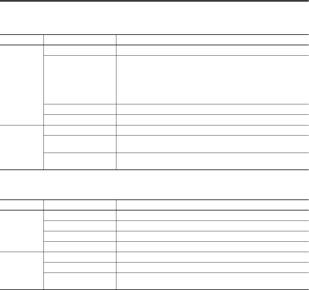
DeviceNet, ControlNet, EtherNet/IP
LED This Pattern: Indicates:
Comm Solid Fill Normal operating state (no communication faults)
No Fill Hardware failed
Flashing When power is first applied (momentarily)
Blinking No communications established
Fault Solid Fill Hardware failed
No Fill Normal operating state (no communication faults)
Blinking Hardware is functioning but no application is loaded or the current application is
corrupt