
User Manual Manual
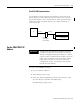
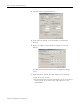
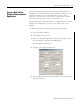
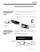
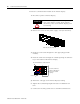
Table Of Contents
- 2706-UM017C-EN-P InView Communications User Manual
- Summary of Changes
- Table of Contents
- 1 - Introduction to InView Connectivity
- 2 - Install InView Communication Modules
- Mount Module to 2706-P42, 2706-P43 and 2706-P44 Displays
- Wire Communication Module to InView Display 2706-P42, 2706-P43, 2706-P44
- Mount Communication Kit to 2706-P72, 2706-P74, 2706-P92 and 2706-P94 Displays
- Wire Communication Kit to 2706-P72, 2706-P74, 2706-P92 and 2706-P94 Displays
- Use Communication Module with a 2706-P22R Display
- 3 - InView Communication Module Connections
- 4 - Application Guide
- ControlNet Communication and Tag Setup Screens
- DeviceNet Communication and Tag Setup Screens
- Data Highway Plus (DH+) Communication and Tag Setup Screens
- DH485 Communication and Tag Setup Screens
- EtherNet Communication and Tag Setup Screens
- RIO Communication and Tag Setup Screens
- Save or Download an Application File
- 5 - InView Communication Module Troubleshooting
- A - InView Communication Module Specifications
- Index
- Back Cover
Publication 2706-UM017C-EN-P - March 2006
2-2 Install InView Communication Modules
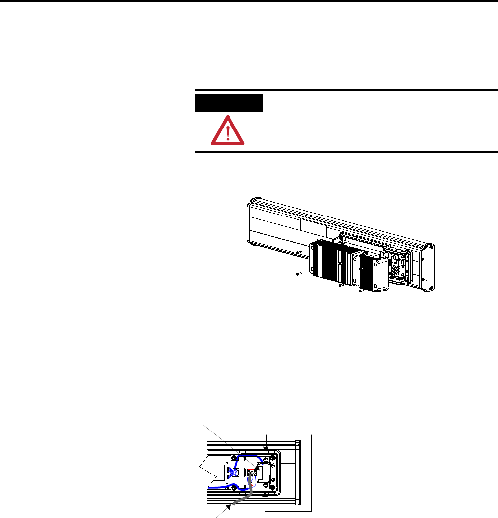
To wire the communication module to the InView display:
1. Disconnect power to InView display.
2. Remove six screws on the power supply cover (on 2706-P4x).
3. Route the serial cable through the cable grip (shipped with
module).
4. Insert the serial wires through the conduit opening on either the
top or the bottom of the InView display.
5. Mount the cable grip to the InView display housing.
6. Tighten the locknut finger-tight and rotate an additional 1/2
turn.
7. Connect the incoming serial wires to the TB1 terminal block.
ATTENTION
Hazardous voltage. Contact with high voltage
may cause death or serious injury. Always
disconnect power to the InView display prior
to servicing.
2706-P42, 2706-P43, 2706-P44
Power Line
Insert the serial wires
with the cable grip into
one of these conduit
openings.
TB1 Terminal Block for serial connection