
User Manual Manual
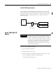
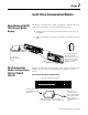
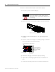
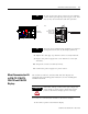
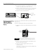
Table Of Contents
- 2706-UM017C-EN-P InView Communications User Manual
- Summary of Changes
- Table of Contents
- 1 - Introduction to InView Connectivity
- 2 - Install InView Communication Modules
- Mount Module to 2706-P42, 2706-P43 and 2706-P44 Displays
- Wire Communication Module to InView Display 2706-P42, 2706-P43, 2706-P44
- Mount Communication Kit to 2706-P72, 2706-P74, 2706-P92 and 2706-P94 Displays
- Wire Communication Kit to 2706-P72, 2706-P74, 2706-P92 and 2706-P94 Displays
- Use Communication Module with a 2706-P22R Display
- 3 - InView Communication Module Connections
- 4 - Application Guide
- ControlNet Communication and Tag Setup Screens
- DeviceNet Communication and Tag Setup Screens
- Data Highway Plus (DH+) Communication and Tag Setup Screens
- DH485 Communication and Tag Setup Screens
- EtherNet Communication and Tag Setup Screens
- RIO Communication and Tag Setup Screens
- Save or Download an Application File
- 5 - InView Communication Module Troubleshooting
- A - InView Communication Module Specifications
- Index
- Back Cover
Publication 2706-UM017C-EN-P - March 2006
2-4 Install InView Communication Modules
2. Open the front of the InView case by turning the latches counter
clockwise and carefully lower the front of the case.
3. Install the Communication Kit (2706-P_K) to the mounting plate
located near TB1 using the supplied standoffs and screws.
4. Torque the screws to 0.68 Nm (6 in-lbs).
Wire Communication Kit to
2706-P72, 2706-P74,
2706-P92 and 2706-P94
Displays
The power to the communication module is provided by the InView
display (series C).
To wire the communication module to the InView display:
1. Connect the serial wires to the TB1 terminal block in the InView
display.
2. Route the customer supplied network cable through the cable
grip and locknut that is provided.
3. Connect the customer supplied network cable to the
Communication Kit.
Verify that there is adequate slack in the cable by making a loop
of cable inside the InView case.
TB1
To TB1
To Controller
(Customer Supplied
Cable)
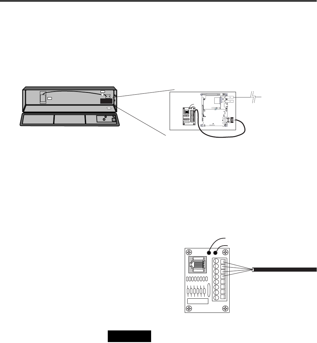
TIP
The 2706-P_K communication kits are powered
through the serial cable by the display (series C).
Black (GND)1
Red (PWR, +5V)2
Orange (TX)3
Brown (RX)4
5
6
7
8