
User Manual Manual
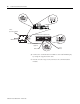
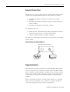
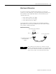
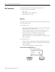
Table Of Contents
- 2706-UM017C-EN-P InView Communications User Manual
- Summary of Changes
- Table of Contents
- 1 - Introduction to InView Connectivity
- 2 - Install InView Communication Modules
- Mount Module to 2706-P42, 2706-P43 and 2706-P44 Displays
- Wire Communication Module to InView Display 2706-P42, 2706-P43, 2706-P44
- Mount Communication Kit to 2706-P72, 2706-P74, 2706-P92 and 2706-P94 Displays
- Wire Communication Kit to 2706-P72, 2706-P74, 2706-P92 and 2706-P94 Displays
- Use Communication Module with a 2706-P22R Display
- 3 - InView Communication Module Connections
- 4 - Application Guide
- ControlNet Communication and Tag Setup Screens
- DeviceNet Communication and Tag Setup Screens
- Data Highway Plus (DH+) Communication and Tag Setup Screens
- DH485 Communication and Tag Setup Screens
- EtherNet Communication and Tag Setup Screens
- RIO Communication and Tag Setup Screens
- Save or Download an Application File
- 5 - InView Communication Module Troubleshooting
- A - InView Communication Module Specifications
- Index
- Back Cover

Publication 2706-UM017C-EN-P - March 2006
Install InView Communication Modules 2-5
4. Mount the cable grip to the InView display housing.
5. Tighten the locknut finger-tight and rotate an additional 1/2
turn.
6. Tighten the cable grip cap until the cable is securely fastened.
7. Carefully close the InView case and tighten the latches by
turning them clockwise.
8. Connect the InView to a power source.
Use Communication
Module with a 2706-P22R
Display
The 2706-P22R InView panel mount display can be used with a
2706-P_P communication module. The module is mounted on a DIN
rail inside the enclosure the 2706-P22R display is mounted. This
maintains the NEMA 4x, 12 or 13 rating. The 2706-P_P communication
module also requires a separate 24V dc power supply. This module
does not receive power from the InView display.
To use the communication module with the InView display:
1. Disconnect power to the enclosure.
2. Mount DIN rail somewhere in the enclosure, near the 2706-P22R
display.
3. Snap the communication module to the DIN rail, and lock the
latches.
4. Connect the customer supplied network cable to the
communication module.