
User Manual Manual
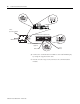
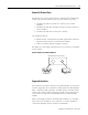
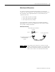
Table Of Contents
- 2706-UM017C-EN-P InView Communications User Manual
- Summary of Changes
- Table of Contents
- 1 - Introduction to InView Connectivity
- 2 - Install InView Communication Modules
- Mount Module to 2706-P42, 2706-P43 and 2706-P44 Displays
- Wire Communication Module to InView Display 2706-P42, 2706-P43, 2706-P44
- Mount Communication Kit to 2706-P72, 2706-P74, 2706-P92 and 2706-P94 Displays
- Wire Communication Kit to 2706-P72, 2706-P74, 2706-P92 and 2706-P94 Displays
- Use Communication Module with a 2706-P22R Display
- 3 - InView Communication Module Connections
- 4 - Application Guide
- ControlNet Communication and Tag Setup Screens
- DeviceNet Communication and Tag Setup Screens
- Data Highway Plus (DH+) Communication and Tag Setup Screens
- DH485 Communication and Tag Setup Screens
- EtherNet Communication and Tag Setup Screens
- RIO Communication and Tag Setup Screens
- Save or Download an Application File
- 5 - InView Communication Module Troubleshooting
- A - InView Communication Module Specifications
- Index
- Back Cover
Publication 2706-UM017C-EN-P - March 2006
2-6 Install InView Communication Modules
5. Connect the communications module to the 2706-P22R display
by using the supplied serial cable.
6. Provide 24 volts ±25 percent, 1A DC to the communications
module.
1 2 3 4 5
6 7 8 9
RS-232
1 2 3 4 5
6 7 8 9
RS-232
24V dc
(Customer Supplied)
24V dc
Class 2
24V dc
DIN Rail
To Controller (Customer Supplied Cable)
2706-NC13 Serial Cable
(Supplied)
Network Port