
User Manual Manual
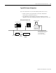
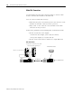

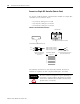

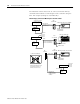
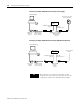
Table Of Contents
- 2706-UM017C-EN-P InView Communications User Manual
- Summary of Changes
- Table of Contents
- 1 - Introduction to InView Connectivity
- 2 - Install InView Communication Modules
- Mount Module to 2706-P42, 2706-P43 and 2706-P44 Displays
- Wire Communication Module to InView Display 2706-P42, 2706-P43, 2706-P44
- Mount Communication Kit to 2706-P72, 2706-P74, 2706-P92 and 2706-P94 Displays
- Wire Communication Kit to 2706-P72, 2706-P74, 2706-P92 and 2706-P94 Displays
- Use Communication Module with a 2706-P22R Display
- 3 - InView Communication Module Connections
- 4 - Application Guide
- ControlNet Communication and Tag Setup Screens
- DeviceNet Communication and Tag Setup Screens
- Data Highway Plus (DH+) Communication and Tag Setup Screens
- DH485 Communication and Tag Setup Screens
- EtherNet Communication and Tag Setup Screens
- RIO Communication and Tag Setup Screens
- Save or Download an Application File
- 5 - InView Communication Module Troubleshooting
- A - InView Communication Module Specifications
- Index
- Back Cover
Publication 2706-UM017C-EN-P - March 2006
3-16 InView Communication Module Connections
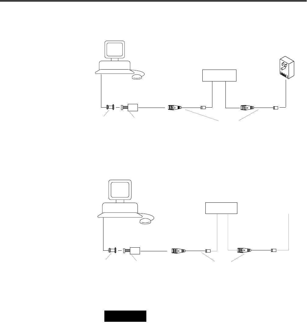
Connecting a Computer to DH-485 Connector Using a Power Supply
Connecting a Computer to DH-485 Connector Using a DH-485 Powered Device
Cable Cat. No.
1747-C10 Cat. No.
1747-C11 Cat. No.
1747-C20
Personal Computer
Interface Converter
(Cat. No. 1747-PIC)
2
5-pin to 9-pin
Adapter (if
required)
Wallmount Power Supply
Cat. No. 1747-NP1
InView Messaging
To DH-485 Programming
Connector
To DH-485
Communications Port
DH-485 Comm
Module
Personal Computer
Interface Converter
(Cat. No. 1747-PIC)
25-pin to 9-pin
Adapter (if
required)
SLC 500 or DH-485
Network
Cable Cat. No.
1747-C10,
1747-C11,
1747-C20
To DH-485 Programming
Connector
To DH-485
Communications Port
InView Messaging
DH-485 Comm
Module
TIP
The computer can connect to any node on the
network. It is not necessary to directly connect the
computer to the InView communication module.