
User Manual Manual
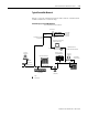
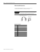
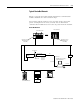
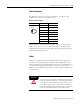

Table Of Contents
- 2706-UM017C-EN-P InView Communications User Manual
- Summary of Changes
- Table of Contents
- 1 - Introduction to InView Connectivity
- 2 - Install InView Communication Modules
- Mount Module to 2706-P42, 2706-P43 and 2706-P44 Displays
- Wire Communication Module to InView Display 2706-P42, 2706-P43, 2706-P44
- Mount Communication Kit to 2706-P72, 2706-P74, 2706-P92 and 2706-P94 Displays
- Wire Communication Kit to 2706-P72, 2706-P74, 2706-P92 and 2706-P94 Displays
- Use Communication Module with a 2706-P22R Display
- 3 - InView Communication Module Connections
- 4 - Application Guide
- ControlNet Communication and Tag Setup Screens
- DeviceNet Communication and Tag Setup Screens
- Data Highway Plus (DH+) Communication and Tag Setup Screens
- DH485 Communication and Tag Setup Screens
- EtherNet Communication and Tag Setup Screens
- RIO Communication and Tag Setup Screens
- Save or Download an Application File
- 5 - InView Communication Module Troubleshooting
- A - InView Communication Module Specifications
- Index
- Back Cover
Publication 2706-UM017C-EN-P - March 2006
3-20 InView Communication Module Connections
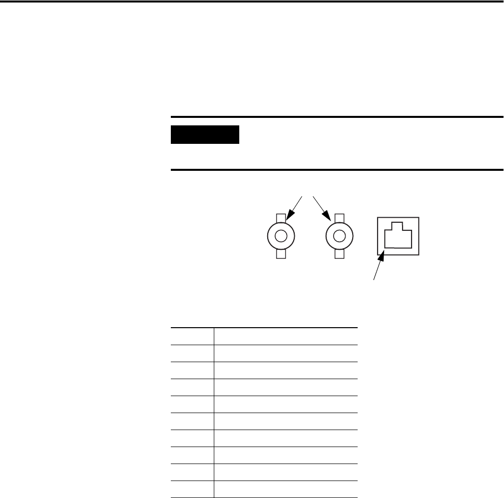
Make ControlNet Connections
Use the pinout information below to connect the InView
communication module to a ControlNet network.
ControlNet Connections
IMPORTANT
Follow the ControlNet network layout and design as
specified in the ControlNet Cable System Planning
and Installation Manual, publication 1786-6.2.
NAP Connector Details
Pin # NAP Signal
1 Signal Common
2 No Connection
3 TX_H
4 TX_L
5 RX_L
6 RX_H
7 No Connection
8 Signal Common
Shell Earth Ground
Channel B Channel A
Pin 1
NAP Connector
Redundant BNC Cable Connectors