
User Manual Manual
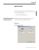
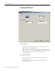
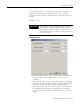
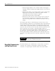
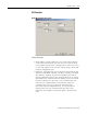
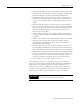
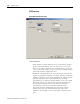
Table Of Contents
- 2706-UM017C-EN-P InView Communications User Manual
- Summary of Changes
- Table of Contents
- 1 - Introduction to InView Connectivity
- 2 - Install InView Communication Modules
- Mount Module to 2706-P42, 2706-P43 and 2706-P44 Displays
- Wire Communication Module to InView Display 2706-P42, 2706-P43, 2706-P44
- Mount Communication Kit to 2706-P72, 2706-P74, 2706-P92 and 2706-P94 Displays
- Wire Communication Kit to 2706-P72, 2706-P74, 2706-P92 and 2706-P94 Displays
- Use Communication Module with a 2706-P22R Display
- 3 - InView Communication Module Connections
- 4 - Application Guide
- ControlNet Communication and Tag Setup Screens
- DeviceNet Communication and Tag Setup Screens
- Data Highway Plus (DH+) Communication and Tag Setup Screens
- DH485 Communication and Tag Setup Screens
- EtherNet Communication and Tag Setup Screens
- RIO Communication and Tag Setup Screens
- Save or Download an Application File
- 5 - InView Communication Module Troubleshooting
- A - InView Communication Module Specifications
- Index
- Back Cover
Publication 2706-UM017C-EN-P - March 2006
4-2 Application Guide
InView Parameters
• Node address. Node address (1 to 99 decimal) of the InView
display on the ControlNet network.
• Interscan Delay. Time interval (in ms) between display updates.
The range is 100 to 1,000 ms. The default is 100. This parameter
determines how frequently the InView display requests
unscheduled data.
Network Node Parameters
• Node Type. The type of controller that the InView display
communicates with.
• Node Address. The node address of the controller on the
ControlNet network.
For a PLC, a valid node address is 1 to 99.
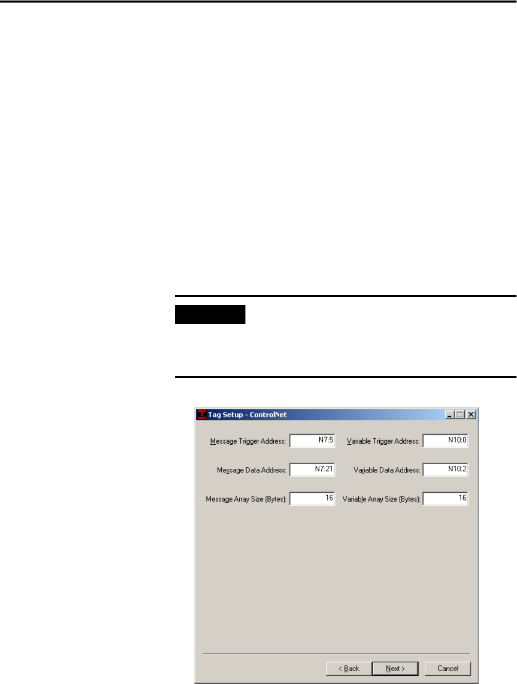
ControlNet Tag Setup
IMPORTANT
All four tags for Message Trigger Address, Message
Data Address, Variable Trigger Address, Variable
Data Address, and the array sizes must be entered
and established in the controller as valid tags even if
they are not used.