
User Manual Manual
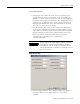


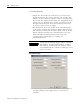
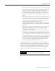

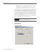

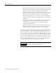
Table Of Contents
- 2706-UM017C-EN-P InView Communications User Manual
- Summary of Changes
- Table of Contents
- 1 - Introduction to InView Connectivity
- 2 - Install InView Communication Modules
- Mount Module to 2706-P42, 2706-P43 and 2706-P44 Displays
- Wire Communication Module to InView Display 2706-P42, 2706-P43, 2706-P44
- Mount Communication Kit to 2706-P72, 2706-P74, 2706-P92 and 2706-P94 Displays
- Wire Communication Kit to 2706-P72, 2706-P74, 2706-P92 and 2706-P94 Displays
- Use Communication Module with a 2706-P22R Display
- 3 - InView Communication Module Connections
- 4 - Application Guide
- ControlNet Communication and Tag Setup Screens
- DeviceNet Communication and Tag Setup Screens
- Data Highway Plus (DH+) Communication and Tag Setup Screens
- DH485 Communication and Tag Setup Screens
- EtherNet Communication and Tag Setup Screens
- RIO Communication and Tag Setup Screens
- Save or Download an Application File
- 5 - InView Communication Module Troubleshooting
- A - InView Communication Module Specifications
- Index
- Back Cover
Publication 2706-UM017C-EN-P - March 2006
4-12 Application Guide
• Message Data Address. The starting address of the message data
displayed. The message data contains the trigger command that
the InView display recognizes (^T[message number]^M).
• Message Array Size. The size of the array (16 to 128 characters
for DeviceNet) containing the message data. The maximum
array size is dependent on the controller and must be an even
integer.
• Message Data Swap Bytes. For DeviceNet, each message data
tag can be set to swap (or not swap) the order of bytes within a
16 bit word. Select the check box to enable swapping. Clear the
check box to disable swapping. You need to check the box
when using a SLC controller or PLC processor.
• Variable Trigger Address. The controller address that triggers a
message variable to display. This toggles between 0 and 1 in the
controller.
• Variable Data Address. The starting address of the variable data
displayed. The variable data contains the update variable
command that the InView display recognizes (^V[variable
data]\[variable number]^M).
• Variable Array Size. The size of the array (16 to 128 characters
for DeviceNet) containing the variable data. The maximum array
size is dependent on the controller and must be an even integer.
• Variable Data Swap Bytes. For DeviceNet, each variable data tag
can be set to swap (or not swap) the order of bytes within a 16
bit word. Select the check box to enable swapping. Clear the
check box to disable swapping. You need to check the box
when using a SLC controller or PLC processor.
The address tags must be an Output data type, in the following
syntax: O:[element number]. Both the Message Trigger and Message
Data addresses must fall entirely within the scanners output size or a
maximum of 64 words, including the Message Data array size. For
example, a Message Trigger address of O:10 and a Message Data
address of O:32, with a scanner output size of 31 is not valid.
IMPORTANT
Variable Trigger and Variable Data addresses work
the same as Variable Data Swap Bytes.