Allen-Bradley DTAM Programming Software Catalog No.
Important User Information Solid state equipment has operational characteristics differing from those of electromechanical equipment. “Safety Guidelines for the Application, Installation and Maintenance of Solid State Controls” (Publication SGI-1.1) describes some important differences between solid state equipment and hard–wired electromechanical devices.
Table of Contents DTAM Programming Software User Manual Using this Manual Chapter 1 Objectives . . . . . . . . . . . . . . . . . . . . . . . . . . . . . . . . . . . . . . . . . . . . . . . . . Contents . . . . . . . . . . . . . . . . . . . . . . . . . . . . . . . . . . . . . . . . . . . . . . . . . . Intended Audience . . . . . . . . . . . . . . . . . . . . . . . . . . . . . . . . . . . . . . . . . . . Conventions . . . . . . . . . . . . . . . . . . . . . . . . . . . . . . . . . . . . . . . . . . . . . .
Table of Contents DTAM Programming Software User Manual Using Screen Builder Chapter 5 Chapter Objectives . . . . . . . . . . . . . . . . . . . . . . . . . . . . . . . . . . . . . . . . . . Screen Builder . . . . . . . . . . . . . . . . . . . . . . . . . . . . . . . . . . . . . . . . . . . . . . Accessing Screen Types . . . . . . . . . . . . . . . . . . . . . . . . . . . . . . . . . . . . . . Editing Screen Displays . . . . . . . . . . . . . . . . . . . . . . . . . . . . . . . . . . . . . . .
Table of Contents DTAM Programming Software User Manual Creating Security Screens Chapter 9 Chapter Objectives . . . . . . . . . . . . . . . . . . . . . . . . . . . . . . . . . . . . . . . . . . Security Screens . . . . . . . . . . . . . . . . . . . . . . . . . . . . . . . . . . . . . . . . . . . . Security Screen Builder . . . . . . . . . . . . . . . . . . . . . . . . . . . . . . . . . . . . . . . Creating a Security Screen . . . . . . . . . . . . . . . . . . . . . . . . . . . . . . . . . . . . .
Table of Contents DTAM Programming Software User Manual Entering DTAM Configuration Data Chapter 14 DTAM Plus Background Monitor Chapter 15 DTAM Micro Function Key Builder Chapter 16 iv Chapter Objectives . . . . . . . . . . . . . . . . . . . . . . . . . . . . . . . . . . . . . . . . . . 14–1 Configuration Parameters . . . . . . . . . . . . . . . . . . . . . . . . . . . . . . . . . . . . . . 14–1 Accessing Configuration Data . . . . . . . . . . . . . . . . . . . . . . . . . . . . . . . . . . .
Table of Contents DTAM Programming Software User Manual DTAM Plus Print Form Builder Chapter 17 DTAM Plus ASCII Bar Code Input Chapter 18 Transferring / Printing Application Files Chapter 19 Upgrading the Operating System Chapter 20 ASCII Character Set Appendix A Chapter Objectives . . . . . . . . . . . . . . . . . . . . . . . . . . . . . . . . . . . . . . . . . . Printer Form Builder . . . . . . . . . . . . . . . . . . . . . . . . . . . . . . . . . . . . . . . . . . Printer Control . . . . . . .
Table of Contents DTAM Programming Software User Manual Data Formats Appendix D Data Formats . . . . . . . . . . . . . . . . . . . . . . . . . . . . . . . . . . . . . . . . . . . . . . Bit Format . . . . . . . . . . . . . . . . . . . . . . . . . . . . . . . . . . . . . . . . . . . . . . . 16 Bit Signed Integer . . . . . . . . . . . . . . . . . . . . . . . . . . . . . . . . . . . . . . . 16 Bit Unsigned Integer . . . . . . . . . . . . . . . . . . . . . . . . . . . . . . . . . . . . . 16 Bit BCD . . . . . .
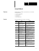
Chapter A–B 1 Using this Manual Objectives Read this chapter to familiarize yourself with the rest of the manual.
Chapter 1 Using this Manual Chapter Title Purpose 14 Entering Configuration Data Describes how to enter configuration data that allows the DTAM to communicate with a controller. 15 DTAM Plus Background Monitor Describes how to monitor controller addresses for displaying alarm or generating printouts on the DTAM Plus. 16 DTAM Micro Function Key Builder Describes how to assign screen navigation or bit write functions to the DTAM Micro function keys.
Chapter 1 Using this Manual Conventions This manual uses the following conventions: • Keys that you press on your personal computer keyboard are enclosed in brackets [ ]. For example: [Esc] refers to the Escape key • Keys that an operator would press on the DTAM Micro or DTAM Plus are also enclosed in brackets but are bold [ ]. For example: [F1] refers to the F1 function key on the DTAM Micro. • [Return] refers to the carriage return key of your computer keyboard.
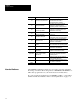
Chapter 1 Using this Manual Related Publications The following publications may be required for additional reference. DTAM Plus and DTAM Micro Publications Publication / Catalog Number 2707-800 DTAM Plus User Manual 2707-803 DTAM Micro User Manual 2707-802 Getting Started With the DTAM Plus Title SLC Publications Publication / Catalog Number 1747-6.21 1747-6.2 1746-6.1 1746-6.2 1746-6.
Chapter A–B 2 Installing / Running DTAM Programming Software Chapter Objectives This chapter describes how to install the DPS software. Menu and screen conventions are also provided.
Chapter 2 Installing / Running DTAM Programming Software Performing Firmware Upgrade with Older Software Versions The incompatibility between firmware and hardware causes the screen to go blank and no communications with the SLC/PLC will occur. You must then upgrade the firmware to the latest level available before the DTAM will respond again.
Chapter 2 Installing / Running DTAM Programming Software Installing DTAM Programming Software This section shows how to install the software on a personal computer with at least 1 hard disk drive and 1 floppy disk drive. The software is supplied on 3 1/2 inch disks. 1. Turn on your computer. Your computer prompt will display the currently active drive: A:, B:, or C: 2. Insert the DPS installation disk into the floppy drive. 3. Select the drive containing the disk (A: or B:) and press [Return].
Chapter 2 Installing / Running DTAM Programming Software Installing DTAM Programming Software 5. Press any key (other than [Esc]) to continue. ☞ You cannot install the DPS software on the same drive on which the Install program resides. 6. Use the ["][#] arrow keys to highlight the drive on which you want to install DPS and then press [Return]. The default drive is C: 2–4 This screen appears. This screen appears.
Chapter 2 Installing / Running DTAM Programming Software ☞ You can specify another directory. The Install program will create the directory if it does not exist. 7. Press [Return] to install the DPS software in the \DPS subdirectory. The Install program creates the subdirectory. If you enter your own subdirectory name, the entire path name including colons, forward slash, and name should not exceed 28 characters. The status of the installation is displayed on the screen.
Chapter 2 Installing / Running DTAM Programming Software Running DPS To run the DTAM Programming Software: ☞ If you installed the software in another subdirectory, move to that directory. 1. Verify that you are at the \DPS subdirectory where the software resides. If you are not, enter cd \DPS and press [Return]. C:\DPS> 2. Type DPS and press [Return] to start the program. C:\DPS> DPS [Return] 3. Specify whether you are using a color monitor. Enter [Y] or [N]. The startup screen displays.
Chapter 2 Installing / Running DTAM Programming Software 4. Select the product type you are creating an application for (DTAM Micro, DTAM Plus, or MicroView) and press [Return]. The Opening Menu appears: Plus, Micro, or MicroView Depending upon selection.
Chapter 2 Installing / Running DTAM Programming Software You are now ready to create a file for your application.
Chapter 2 Installing / Running DTAM Programming Software Menu Conventions Figure 2.1 shows the format of DPS menu screens: Figure 2.1 DPS Menu Screen Format Menu Window The Menu Window lists operations available at the current menu. To select one of the operations, highlight the operation and press [Return]. Operations Windows The Operations Window displays keyboard operations available at the current Menu Window.
Chapter 2 Installing / Running DTAM Programming Software Screen Building Conventions Figure 2.2 shows the Screen Builder format: Figure 2.2 Screen Builder Format There are two information lines at the top of the screen: • The first line identifies the current program path and file name, as well as screen memory usage to help you track the size of your program file. • The second line identifies the current DPS operating area as well as the current screen number and type.
Chapter 2 Installing / Running DTAM Programming Software Cursor Status Line The cursor status line is located between the Display and Information windows. This line displays the current row and column of the cursor. Also listed is the character at that position along with the character ASCII code in hex and decimal formats. Confirm character codes by placing the cursor under the character and reading the code from the cursor status line. The following example shows the character C at row 2, column 15.
Chapter A–B 3 Designing DTAM Plus and DTAM Micro Applications Objectives This chapter describes the differences between DTAM Micro and DTAM Plus applications. Also provided are guidelines for creating applications.
Chapter 3 Designing DTAM Plus and DTAM Micro Applications DTAM Plus / DTAM Micro Comparison Both the applications are created using DPS. The development of applications for the DTAM Micro and DTAM Plus is very similar. This manual shows screens for DTAM Plus applications, the DTAM Micro screens are similar unless noted. The differences in application development are related to differences in the operator terminals. The following table lists these differences.
Chapter 3 Designing DTAM Plus and DTAM Micro Applications DTAM Plus / DTAM Micro File Types Both the DTAM Micro and DTAM Plus can read and write PLC and SLC controller files. Refer to the following when designing applications.
Chapter 3 Designing DTAM Plus and DTAM Micro Applications Screen Types and Data Formats Some application screens require that you specify register information. Each DTAM screen type supports different data formats. The following table lists each screen type and the data formats supported.
Chapter 3 Designing DTAM Plus and DTAM Micro Applications SLC Data Formats Display, Alarm, Printer Form ➀ Screens Data Entry Screens Bit n n 16 Bit Signed Integer n n 16 Bit Unsigned Integer n n 16 Bit BCD n n 16 Bit Hex n 32 Bit Unsigned Integer n n n 32 Bit BCD n n n 32 Bit Hex n ASCII n Format Bar Graph Background Screens ➀ Monitor ➀ Recipe Screens n n n n n n n n ➀ Bar Graph, Printer Form, and Background Monitor are only available on DTAM Plus Operator Modules.
Chapter 3 Designing DTAM Plus and DTAM Micro Applications Data Scaling Data entered by an operator can be scaled from engineering units such as gallons or PSI to machine control values. Likewise, data displays can take raw numeric values and scale them so they are displayed in engineering units. Scaling of data is accomplished by defining a proportional ratio between the register value range and the display or entry value range.
Chapter 3 Designing DTAM Plus and DTAM Micro Applications Scaling Formulas The scaling formula for a DTAM display value is: Displayed Value = m x Register Value + b Where: m= Display Maximum Value – Display Minimum Value Register Maximum Value – Register Minimum Value b= Display Minimum Value – ( m x Register Minimum Value ) The scaling formula for an entered valued is: Register Value = m x Entered Value + b Where: m= Register Maximum Value – Register Minimum Value Entry Maximum Value – Entry Mini
Chapter 3 Designing DTAM Plus and DTAM Micro Applications Application Example The following example shows typical menus and screens of a DTAM Plus application. The same application could be created on a DTAM Micro with the following exceptions: • DTAM Micro screen is 2 lines by 20 characters. Large screens would have to be shortened or broken down into separate screens. • The DTAM Micro cannot support a bar graph screen. DTAM Plus Application Outline Main Menu 1. Pump/Tank Levels 2. Pump Control 3.
Chapter 3 Designing DTAM Plus and DTAM Micro Applications Example Application Description Pump/Tank Levels When Pump/Tank Levels is selected from the Main Menu, a Sub-Menu displays two new choices (East Pump/Tank and West Pump/Tank). Selecting either of these Sub-Menu items allows you to display pump and tank information for the East or West systems. Pump Control Allows you to enter new pump setpoints to be entered. A security code is required to access the Data Entry screens.
Chapter 3 Designing DTAM Plus and DTAM Micro Applications Designing an Application Appendix B contains worksheets for designing both DTAM Micro and DTAM Plus applications. Both application layout and screen design worksheets are provided. Use the application design worksheets to layout a logical sequence of screens. Make copies of the worksheets as needed. On each worksheet, list the screen numbers, type of screens, register numbers, etc.
Chapter 3 Designing DTAM Plus and DTAM Micro Applications Recommended sequence for creating an application: Step 1 On paper, design all the operator screens with the associated register numbers, and produce a map of how all screens are linked together. Step 2 Construct all screens using DPS. Save the program file without linking. Step 3 Link the application screens. Use the design from step 1. When you have established all links, save the program file.
Chapter A–B 4 Creating or Editing an Application File Chapter Objectives This chapter describes how to open, edit and save an application file. Section Opening Menu Page Opening Menu 4–1 Edit Application File 4–2 Save Application File 4–4 The Opening Menu is the first menu displayed each time you run the software. Note: If you specified prompts for monitor type and product type during installation, these prompts will appear before the opening menu.
Chapter 4 Creating or Editing an Application File Edit Application File To create or edit an application: 1. Select Edit Program File to create or edit a DTAM application file. You are prompted for the file name to edit or create. All DTAM application files in the current directory are listed. The directory only lists files compatible with the currently specified hardware type. For example, if DTAM Micro is specified only DTAM Micro applications are listed.
Chapter 4 Creating or Editing an Application File After you select an existing file or enter the operating system (for new files), the Edit File - Option Selection menu is displayed. DTAM Micro or MicroView or DTAM Plus 3. Access the following functions from the Edit File - Option Selection menu to create your application screens and enter configuration data.
Chapter 4 Creating or Editing an Application File Select this Menu Option: DTAM Configuration Data ✓ Screen Builder ✓ Alarm Screen Builder ✓ Background Monitor ✓ Print Form Builder ✓ Function Key Builder Save Application File Applies to: DTAM- Micro- DTAMView Micro Plus ✓ ✓ ✓ ✓ ✓ ✓ To Set configuration and operating parameters. Create or modify application screens. Create or modify alarm screens. Assign background registers and limits for the DTAM Plus to monitor.
Chapter 4 Creating or Editing an Application File 2. Press [Return] to save the application under the file name entered when the application file was opened. Or enter a new file name: If you were creating a new file, the new file name replaces the file name entered when the application was opened. If you are editing an existing file, the original file is unchanged. The file and all edits made prior to the last save are stored under the new file name. 3.
Chapter A–B 5 Using Screen Builder Chapter Objectives This chapter describes options common to all of the Screen Builder types. Section Screen Builder Page Screen Builder 5–1 Accessing Screen Types 5–2 Editing Screen Displays 5–4 Copying Screens 5–5 Selecting Other Screens 5–6 Clearing Screens 5–7 Inserting Time or Date 5–8 Exiting Screen Builder 5–9 Screen Builder is one of the menu items available when you select Edit Program File from the Opening menu.
Chapter 5 Using Screen Builder Accessing Screen Types To access Screen Builder screens: 1. Select Screen Builder from the Edit File - Option Selection menu. The Screen Builder for the main menu screen (screen #1) displays: 2. If you have designed your main menu screen, you can create it now as described in Chapter 6. Each application must have a main menu screen. If you want to create another screen type, proceed to the next step.
Chapter 5 Using Screen Builder 3. Press [F8] on any screen to access the other screen types. You are prompted for a screen number: Press [F6] to go to the next available unused screen or [F8] to view the contents of the next programmed screen. 4. If you enter any screen number other than screen #1 (main menu screen), you are prompted for a screen type: 5. Select a screen type. A Screen Builder for the selected screen type is then displayed. Refer to Chapters 6 through 11.
Chapter 5 Using Screen Builder Editing Screen Displays When you are editing screen text, the following editing operations are available: Screen Text Edit Functions Screen Edit Key Arrow keys [°] [±] [²] [³] [Del] Function Move the screen cursor. Deletes the character at the cursor position. [Back Space] [Ins] Deletes the character to the left of the cursor position. The cursor is moved to the left one space. Toggles the insert mode on or off.
Chapter 5 Using Screen Builder Copying Screens Use the copy function [F4] to save time when creating similar screens. Both the source screen and the destination screen must be of the same type. For example, you can’t copy Data Entry screen text into a Data Display screen. When you copy a screen, all register data and display text is also copied. Edit the screen as needed after copying. To copy a screen: 1. Open the screen you want to copy the screen to or from. In this example a Data Display screen: 2.
Chapter 5 Using Screen Builder Selecting Other Screens After you have completed an application screen, use [F8] Change Screen to edit another screen. You can change to any screen except an alarm screen. Use the Alarm Builder function (Chapter 13) to access alarm screens. To change screens: 1. Select [F8] Change Screen. You are prompted for a screen number. 8 2.
Chapter 5 Using Screen Builder Clearing Screens Use the [F7] Clear Screen function to clear all or part of the currently displayed screen. To clear a screen: 1. Open the screen you want to clear. 2. Select [F7] Clear Screen. You are prompted for a clear screen option: 8 3. Select the Clear Screen option. Press: To: ENTER [Return] Clear the display text only. Screen linking and register data for the screen are not deleted.
Chapter 5 Using Screen Builder Inserting the Time or Date If you are programming a DTAM Plus with a clock/calendar option, you can insert the time or date into any application screen. Time and date functions are not available on the DTAM Micro. The time field takes up 5 character positions and is displayed in the format HH:MM. AM/PM and seconds are not displayed to conserve space. However AM/PM and the seconds are shown on print forms in the format HH:MM:SS AM.
Chapter 5 Using Screen Builder Exiting Screen Builder You can exit Screen Builder at any time during the design of an application. Screen edits are not lost when you exit Screen Builder, however, we recommend that you press [F9] SAVE before exiting. To exit Screen Builder: 1. Press [Esc]. If you haven’t established screen linking, you are provided a reminder: 2. Press [Y] to acknowledge the reminder (if displayed). After exiting Screen Builder, the Edit File - Option Selection menu is displayed.
Chapter A–B 6 Creating Menu and Sub-Menu Screens Chapter Objectives This chapter describes how to create the main menu and sub-menu screens. Section Menu Screens Page Menu Screens 6–1 Building a Menu 6–2 Main Menu and Sub-Menu Screen Builder 6–3 Creating a Menu Screen 6–4 Menu Screens provide easy access to different parts of an application. Menus structure an application on the basis of specific tasks and responsibilities. Each menu screen may consist of up to 8 different menu items.
Chapter 6 Creating Menu and Sub-Menu Screens Building a Menu When you build a menu, you are directing the operator to more specific screens. A menu is a numbered list of components available at the current stage of a process. Number each successive menu entry sequentially. The number tells the operator which DTAM keypad key ([1] through [8]) to press for each menu item (1 through 8). The following example shows the menu structure of a DTAM Plus application.
Chapter 6 Creating Menu and Sub-Menu Screens Main Menu and Sub-Menu Screen Builder The screen for creating the main menu and sub-menu screens is the same for the DTAM Plus and DTAM Micro. The only difference is the DTAM Micro has a 2 line display and the DTAM Plus can display 4 lines.
Chapter 6 Creating Menu and Sub-Menu Screens Creating a Menu Screen To create a menu screen: 1. Select Screen Builder from the Edit File - Option Selection menu. The screen builder for the main menu (screen #1) is displayed. 2. If you are creating a sub-menu, press [F8], enter the screen number, and select a sub-menu screen type. The screen builder for a sub-menu is displayed. The sub-menu screen builder is the same as the main screen (shown above). 3. Enter the screen text.
Chapter A–B 7 Creating Data Display Screens Chapter Objectives This chapter describes how to create data display screens. Section Data Displays Page Data Displays 7–1 Scaling 7–1 Data Display Screen Builder 7–2 Inserting Display Data 7–3 Display Register Format Selections 7–5 Data display screens allow you to monitor the value of registers in the SLC or PLC. The DTAM continuously reads the registers to update (at a userdefined rate) the displayed values.
Chapter 7 Creating Data Display Screens Data Display Screen Builder The screen for creating data display screens is the same for the DTAM Plus and DTAM Micro. The only exceptions are the DTAM Micro display does not show the time and date function keys and has a smaller display size (2 lines of 20 characters). Data Display Screen Builder Function Keys Applies to: Function Key Designation [F1] DISPLAY REG [F3] MAP SCREEN DTAM Plus DTAM Micro ✓ ✓ Inserts data display field at the cursor point.
Chapter 7 Creating Data Display Screens Creating a Display Screen The display register data field may be inserted anywhere on the screen. The number of positions required for the data field depends upon the register information you provide. You can insert the display data while you are entering the screen text or you can leave spaces and insert the data field later. To create a data display: 1. Select Screen Builder from the Edit File - Option Selection menu.
Chapter 7 Creating Data Display Screens 5. Select a register type. You are prompted for data specific to the selected register type: 16 Bit Signed Integer Shown 6. Enter the register data. Refer to the next section Display Register Format Selections. 7. After entering the register data, press [Esc] to save the data and return to the screen editing. The data display register field is indicated by a series of asterisks ****.
Chapter 7 Creating Data Display Screens Display Register Format Selections When inserting a data display field, you must provide register information that determines the address and format of the data being displayed. This section describes options available for data display registers. Bit The register information for a Bit display is shown below. Refer to Appendix D for default bit text. SLC or PLC depending upon protocol.
Chapter 7 Creating Data Display Screens Display Register Format Selections 16 Bit Signed Integer, 16 Bit Unsigned Integer, 16 Bit BCD (Binary Coded Decimal) The screen for a 16 Bit Unsigned Integer format is shown below. The screens for 16 Bit Signed Integer and 16 Bit BCD formats are similar. SLC or PLC depending upon protocol. Format Selection Register Number 7–6 Description The controller address from which the integer will be monitored.
Chapter 7 Creating Data Display Screens 16 Bit Binary Data Display (DTAM Plus DH485 only) A new data type for data display screens has been added. The new selection 16 BIT BINARY displays a 16 bit binary value with a space between every four bits (nibble). For example: 1010 1011 1100 1101. The most significant bit is at the left, and the least significant bit is at the right. After selecting the 16 BIT BINARY data display, you must enter the register number.
Chapter 7 Creating Data Display Screens 32 Bit Floating Point Important: 32 bit floating point is supported on the DTAM Plus if PLC-5 DF1, DH485, or Remote I/O protocol has been selected. See Appendix D for DTAM Micro floating point format. The screen for a 32 Bit Floating Point format is shown below. Format Selection Register Number 7–8 Description The PLC address to be monitored. Minimum Register Value The minimum data value of the PLC address.
Chapter 7 Creating Data Display Screens Display Register Format Selections 32 Bit Unsigned Integer, 32 Bit BCD (Binary Coded Decimal) The screen for a 32 Bit BCD format is shown below. The screen for a 32 Bit Unsigned Integer format is similar. SLC or PLC depending upon protocol. Format Selection Register Number Description The controller address to be monitored. Digits Right of Decimal The number of digits to be placed to the right of the decimal.
Chapter 7 Creating Data Display Screens 16 Bit HEX (Hexadecimal), 32 Bit HEX The screen for a 32 Bit Hex format is shown below. The screen for a 16 Bit Hex format is similar. SLC or PLC depending upon protocol. Format Selection Register Number 7–10 Description The controller address to be monitored.
Chapter 7 Creating Data Display Screens Display Register Format Selections ASCII The screen for an ASCII format is shown below: SLC or PLC depending upon protocol. Format Selection Description Register Number The controller address to be monitored. Character Count The number of characters (2 characters for each 16 bit data address) to be displayed, up to a maximum of 20 characters.
Chapter A–B 8 Creating Data Entry Screens Chapter Objectives This chapter describes how to create data entry screens Section Data Entry Screens Page Data Entry Displays 8–1 Scaling 8–1 Data Entry Screen Builder 8–2 Creating a Data Entry Screen 8–3 Data Entry Register Format Selections 8–6 Data entry screens allow an operator to directly enter values into SLC or PLC registers. Data entry screens can also contain a data display field.
Chapter 8 Creating Data Entry Screens Data Entry Screen Builder The screen for creating data entry screens is the same for the DTAM Plus and DTAM Micro. The only exceptions are the DTAM Micro display does not show the time and date function keys and has a smaller display size (2 lines of 20 characters).
Chapter 8 Creating Data Entry Screens Creating a Data Entry Screen The entry register data field may be inserted anywhere on the screen, however, no text may follow the data entry field. This means that you must insert any text or a display field before the data entry field. The number of character positions required for the data entry field depends upon the register information you provide. To create a data entry screen: 1. Select Screen Builder from the Edit File - Option Selection menu.
Chapter 8 Creating Data Entry Screens Creating a Data Entry Screen 5. Press [F2] to insert a data entry register. You are prompted to select a register type. The selection depends upon the protocol that was selected. Refer to page 3–3 for a list of the applicable register types for each. 6. Select a register type. You are prompted for data specific to the selected register type: 16 Bit Signed Integer Shown 7. Enter the register data. Refer to the next section Data Entry Register Format Selections.
Chapter 8 Creating Data Entry Screens 8. After entering the register data, press [Esc] to save the data and return to the screen editing. The data entry register field is indicated by a series of diamonds zzzz. The number of diamonds and format (decimal point and sign) is determined by the register data you entered. Data Entry Register 9. Press [F9] to save the screen, any text entered after the data entry field will not be displayed.
Chapter 8 Creating Data Entry Screens Data Entry Register Format Selections When inserting a data entry field, you must provide register information that determines the address and format of the data storage location. This section describes options available for data entry registers. If a data display is included on a data entry screen, the data display value is only updated when the screen is entered. Data does not update continuously.
Chapter 8 Creating Data Entry Screens 16 Bit Signed Integer, 16 Bit Unsigned Integer, 16 Bit BCD (Binary Coded Decimal) The screen for a 16 Bit Unsigned Integer format is shown below. The screens for 16 Bit Signed Integer and 16 Bit BCD formats are similar. SLC or PLC depending upon protocol. Format Selection Register Number Description The controller data address to be monitored. Digits Right of Decimal The number of digits to be placed to the right of the decimal.
Chapter 8 Creating Data Entry Screens 16 Bit Binary Data Entry (DTAM Plus DH485 Only) A new data type for data entry screens has been added. The new selection 16 BIT BINARY displays a 16 bit binary value with a space between every four bits (nibble). A default value may be provided for the data entry field. For example: 0001 0010 0011 0100.
Chapter 8 Creating Data Entry Screens Data Entry Register Format Selections 32 Bit Floating Point Important: 32 bit floating point is an option on a DTAM Plus with PLC-5 DF1, DH485, or RIO protocol selected. See Appendix D for DTAM Micro Floating Point format. The screen for a 32 Bit Floating Point format is shown below. Format Selection Register Number Description The PLC address to be monitored. Minimum Register Value The minimum data value of the controller address being monitored.
Chapter 8 Creating Data Entry Screens 32 Bit Unsigned Integer, 32 Bit BCD (Binary Coded Decimal) The screen for a 32 Bit Unsigned Integer format is shown below. The screen for a 32 Bit BCD format is similar. SLC or PLC depending upon protocol. Format Selection Register Number The controller data address to be monitored. Digits Right of Decimal The number of digits to be placed to the right of the decimal. Digits Left of Decimal The number of digits to be placed to the left of the decimal.
Chapter 8 Creating Data Entry Screens ASCII Input The screen for ASCII input through the printer port (only on some versions) is shown below. Note: Refer to Chapter 18 for additional information on using ASCII bar code input. SLC or PLC depending upon protocol. Format Selection Description Register Number The controller data address to be written. Character Count The number of characters (1 to 32) that are expected for each entry.
Chapter A–B 9 Creating Security Screens Chapter Objectives This chapter describes how to create security screens. Section Security Screens Page Security Screens 9–1 Security Screen Builder 9–2 Creating a Security Screen 9–3 Security screens use numeric codes to restrict access to any associated information or processes.
Chapter 9 Creating Security Screens Security Screen Builder The screen for creating security screens is similar for the DTAM Plus and DTAM Micro. Security Screen Builder Function Keys Applies to: Function Key Designation DTAM Plus DTAM Micro [F1] EDIT CODES ✓ ✓ Allows previously entered codes to be edited. [F3] MAP SCREEN ✓ Accesses screen mapping functions that link application screens in a logical sequence. Link screens only after all of the screens have been created. Refer to Chapter 12.
Chapter 9 Creating Security Screens Creating a Security Screen You can specify up to three separate codes for each Security Screen. An operator is allowed access by entering any of the assigned security codes. Access is also allowed by entering the Master Security Code. To create a security screen: 1. Select Screen Builder from the Edit File - Option Selection menu. The Screen Builder for the main menu (screen #1) is displayed. 2. Press [F8], enter the display screen #, and select Security Screen type.
Chapter A–B 10 Creating Recipe Screens Chapter Objectives This chapter describes how to create recipe screens. Section Recipe Screens Page Recipe Screens 10–1 Recipe Screen Builder 10–2 Creating a Recipe Screen 10–3 Recipe Screens allow an operator to download a block of data for up to 10 register addresses. These addresses can be in any order.
Chapter 10 Creating Recipe Screens Recipe Screen Builder The screen for creating recipe screens is similar for the DTAM Plus and DTAM Micro. The default prompt for operator acknowledgement is different due to differences in the DTAM Plus and DTAM Micro keypads. DTAM Micro Default Prompt Recipe Screen Builder Function Keys Applies to: Function Key Designation [F3] MAP SCREEN DTAM Plus 10–2 Function ✓ Accesses screen mapping functions that link application screens in a logical sequence.
Chapter 10 Creating Recipe Screens Creating a Recipe Screen To create a recipe screen: 1. Select Screen Builder from the Edit File - Option Selection menu. The Screen Builder for the main menu (screen #1) is displayed. 2. Press [F8], enter the display screen #, and select Recipe Screen type. The Screen Builder for a recipe screen appears. You are asked whether the operator is to be prompted before the recipe data is downloaded (manual or automatic operation). 3. Enter [Y] or [N] and press [Return].
Chapter 10 Creating Recipe Screens 4. Select a register type. You are prompted to enter the registers and the values you want to write. 5. Enter the register address and press [Return]. Enter the value to send and press [Return]. Repeat for up to 9 more addresses that you want to write at download. 6. After entering the download data and addresses, press [Esc] to accept the data. 7. Enter the screen text. If an operator prompt was selected, you cannot edit the prompt text. 8.
Chapter A–B 11 Creating Bar Graph Screens Chapter Objectives This chapter describes how to create bar graph screens for DTAM Plus applications. Bar graph screens are not available on DTAM Micro operator modules.
Chapter 11 Creating Bar Graph Screens Bar Graph Screen Builder The bar graph screen is only available on the DTAM Plus. The bar graph Screen Builder looks like this: Bar Graph Screen Builder Function Keys Function Key 11–2 Designation Function [F1] DISPLAY BAR REG Inserts data display field at the cursor point. Accesses the display register information. [F2] EDIT BAR DATA [F3] MAP SCREEN Accesses screen mapping functions that link application screens in a logical sequence.
Chapter 11 Creating Bar Graph Screens Graph Display Range The bar graph can correspond to any range of values within the minimum and maximum values stored in a register. In this way, you can present the optimum control for an operator. For example, if a register has values between 0 and 9999 that correspond to -300°F to 1000°F. For register data, enter 0 and 9999 for the low and high register limits, and -300°F and 1000°F for the display limits (the range shown the operator).
Chapter 11 Creating Bar Graph Screens Creating a Bar Graph Screen To create a bar graph screen: 1. Select Screen Builder from the Edit File - Option Selection menu. The Screen Builder for the main menu (screen #1) is displayed. 2. Press [F8], enter the display screen #, and select Bar Graph Screen type. The Screen Builder for a bar graph screen appears and you are prompted for a register type 16 Bit Signed Integer or 16 bit BCD. 3. Select a register type. You are prompted for the register information. 4.
Chapter 11 Creating Bar Graph Screens 6. Enter the screen text or if you want to add a data display field, press [F1]. The data displayed is the same register value shown in a graphical form on the bar graph. The display window shows an asterisk (*) for each character displayed as register data, and a sign (if specified). For example, the display data for a Signed Integer register having two characters to the right of the decimal and three to the left and sign would be: Display Data 7.
Chapter 11 Creating Bar Graph Screens Bar Graph Register Format Selections The screen for a 16 Bit Signed Integer register is shown below. The screen for a 16 Bit BCD register is similar. SLC or PLC depending upon protocol. Format Selection Register Number Digits Right of Decimal The number of digits to be placed to the right of the decimal. Digits Left of Decimal The number of digits to be placed to the left of the decimal.
Chapter A–B 12 Linking Menu and Application Screens Chapter Objectives This chapter describes how to link the application screens so that an operator is presented with a logical flow of information.
Chapter 12 Linking Menu and Application Screens Linking Menu Screens Menu and sub-menu links provide one way links with up to 8 application screens or sub-menus. An operator selects a menu item by pressing the numeric key corresponding to the menu item. When you link the main menu and sub-menu items you are linking screens to the keys on the numeric keypad. 1. Menu 3. Level 2.
Chapter 12 Linking Menu and Application Screens Application Screen Linking Function Keys When you press [F3] MAP Screen on a non-menu screen, the screen linking function keys are active. Shown below is an example using a bar graph screen, the other screen types are similar. Current Links Screen Link Function Keys Screen Linking Function Keys Applies to: Menu and Sub-Menu Linkage Display DTAM Plus DTAM Micro ✓ ✓ Inserts a link between two screens.
Chapter 12 Linking Menu and Application Screens Linking a Menu The following is a typical example of how to link items to a main menu. Links to a sub-menu are done in the same manner. To link screens to a menu: 1. Open the menu or sub-menu screen. Previously entered text, refer to Chapter 6 2. Press [F3] to select the link screens function. You are prompted to enter a screen number. 3. Enter the screen # you want linked to numeric entry key [1] and press [Return].
Chapter 12 Linking Menu and Application Screens Linking Example The following is an example of how to create one way or bidirectional screen links. To link application screens: 1. Open the screen you want to link. In this example we are linking screen #16 (bar graph display) to screen # 33 (numeric entry screen). 2. Press [F3] to select the MAP Screen function. The current screen links are displayed along with the screen linking function key operations. Indicates that this screen is not linked to a menu.
Chapter 12 Linking Menu and Application Screens 4. Enter a screen number (in this example screen #33) and press [Return]. The screen link is shown in the Screen Linkage description. 5. Press [F9] to save the screen edits. When you open the screen that was just linked (#33), the Screen Linkage description will show that there is now a previous screen link to that screen.
Chapter A–B 13 Creating Alarm Screens Chapter Objectives This chapter describes how to create an alarm screen. It contains these sections: Section Alarm Screens Page Alarm Screens 13–1 Alarm Screen Builder 13–3 Creating an Alarm Screen 13–4 Alarm screens identify cautionary or emergency conditions. Alarm screens are much like data display screens with two exceptions: • Alarm screens cannot be linked together. • They can contain an alarm acknowledge sent back to the SLC or PLC.
Chapter 13 Creating Alarm Screens DTAM Micro Alarm Screens A typical alarm screen appears like this on the DTAM Micro: Motor Overload PRESS ENTER TO CLEAR The last line of an alarm screen automatically defaults to: Press Enter to Clear. If you edit this text, make sure that the operator knows to press the [ ] key to clear the alarm.
Chapter 13 Creating Alarm Screens Alarm Screen Builder The screen builder for DTAM Plus alarm screens is shown below. The alarm screen builder for DTAM Micro is similar. Alarm Function Keys Applies to: DTAM Plus DTAM Micro Function Key Designation [F1] DISPLAY REG ✓ ✓ Inserts data display field at the cursor point. Accesses the display register information. [F3] ACKNOWLEDGE ✓ ✓ Defines the acknowledge bit sent to the controller when the operator acknowledges an alarm.
Chapter 13 Creating Alarm Screens Creating an Alarm Screen To create an alarm screen: 1. Select Edit Program File from the Opening menu: You are prompted for a file name. 2. Enter the file name of the application. The Edit File - Option Selection menu is displayed. 3. Select Alarm Screen Builder. You are prompted for a screen number of the first alarm screen.
Chapter 13 Creating Alarm Screens 4. Enter a screen number. The screen builder for an alarm screen is displayed. 5. Enter the alarm message text. If you are entering a display field, press [F1] where you want the field positioned. Refer to Chapter 7 for information on how to setup a display field. 6. If you want to set an acknowledge bit at the controller when an operator acknowledges an alarm, press [F3]. You are prompted for the acknowledge bit register information.
Chapter 13 Creating Alarm Screens 16 Bit Binary Data 16 BIT BINARY display data can be used on alarm screens. The new 16 BIT BINARY displays a 16 bit binary value with a space between every four bits (nibble). For example: 1010 1011 1100 1101.
Chapter A–B 14 Entering DTAM Configuration Data Chapter Objectives This chapter describes how to set the configuration parameters of the DTAM Plus or DTAM Micro.
Chapter 14 Entering DTAM Configuration Data Accessing Configuration Data The following shows how to access DTAM Plus configuration data. The procedures for the DTAM Micro are similar. 1. Select Edit Program File from the Opening menu. You are prompted for a file name. 2. Enter the file name of the application. The Edit File -Option Selection menu displays. 3. Select DTAM Configuration Data. The DPS Configuration -Option Selection menu displays.
Chapter 14 Entering DTAM Configuration Data Update Interval The update interval specifies the DTAM display update rate. The Update Interval is the period of time between read and write requests to the controller. This is not the rate at which data is read from or written to a controller. When you select Update Interval from the DPS Configuration - Option Selection menu, the following is displayed: To assign a new update interval, enter a valid number from 0.05 to 12.50 seconds in any increment of 0.
Chapter 14 Entering DTAM Configuration Data DTAM Advisor The Advisor function allows screen changes to be made by the logic controller. Alarm screens can also be triggered by the Advisor function. The advisor consists of a controller address monitored by the DTAM. When the advisor address contains a screen number, the corresponding screen is displayed.
Chapter 14 Entering DTAM Configuration Data Advisor Operation The following shows how the Advisor function operates. The controller program must reset the ACK and NAK bits after writing a screen number. ➀ Controller writes screen number to assigned Read Register. ➃ Controller monitoring ACK bit clears ACK/NAK bits for next screen number. ➁ DTAM reads advisor read register and displays corresponding screen (if valid).
Chapter 14 Entering DTAM Configuration Data Time Synchronization Only available on the DTAM Plus with the Clock/Calendar option, this setting controls synchronization between a DTAM Plus and a PLC-5 or SLC controller. The time is synchronized between the DTAM Plus and controller approximately every 60 seconds. The time synchronization does not update when the DTAM is in the P-A/D mode (see Appendix C) or while a data entry screen is displayed.
Chapter 14 Entering DTAM Configuration Data PLC-5 Read/Write Time Registers The DTAM Plus reads and writes the time to the following fixed registers. Location S:18 S:19 S:20 S:21 S:22 S:23 Contents Year Month Day Hours Minutes Seconds SLC Read/Write Time Registers The time data register is a 16 bit integer format. Time/Date data is stored in each of the eight sequential registers as shown below. The register locations are defined by the Time Base Register (see previous page).
Chapter 14 Entering DTAM Configuration Data Setting Master Security Code The master security code is used by an operator to access and/or change the security codes of the security screens. When you select Master Code from the DPS Configuration - Option Selection menu, the following is displayed: Enter a new security code. There are two codes that perform special functions: 00000000 disables the security function. This allows an operator to enter any number as a valid access code.
Chapter 14 Entering DTAM Configuration Data Special Security Screen The special security screen restricts access to the special menu item on the DTAM Mode menu. The DTAM special functions menu allows an operator to directly access controller data files and other controller functions. Providing a security screen protects against unintended use of these functions. If you don’t provide a special security screen, the special functions menu is available to any operator.
Chapter 14 Entering DTAM Configuration Data Printer Port Parameters Only available on a DTAM Plus with an optional printer port. Use this screen to set the operating parameters of the printer port. When you select Printer Port from the DPS Configuration - Option Selection menu, the following is displayed: Baud Rate Default is 9600 baud. Baud rate options are 38400, 19200, 9600, 4800, 2400, 1200, and 300. Select a baud rate that matches your printer. Parity Default is Even parity.
Chapter 14 Entering DTAM Configuration Data SLC Hardware Parameters When using AB DH485 or AB BASIC protocols, you must specify the operating parameters that allow the DTAM Plus or DTAM Micro to communicate with the SLC controller. The DTAM settings must match the settings of the SLC or DH-485 network. If you are communicating with a PLC-5, refer to the next section PLC Hardware Parameters.
Chapter 14 Entering DTAM Configuration Data SLC Hardware Parameters SLC Com Port Setup Selecting Com Port Setup displays: The Communications Port parameters have the following default values for an SLC: Baud Rate: Parity: Data Bits: 19200 Even 8 Baud Rate Default is 19200 baud. Baud rate options are 38400, 19200, 9600, 4800, 2400, 1200, and 300. Select a baud rate that matches your SLC.
Chapter 14 Entering DTAM Configuration Data SLC 500 Slot Configuration Selecting the SLC 500 Slot Configuration allows you to specify the slot configuration so that input and output bit files are correctly mapped. Note: The Slot Configuration table must be properly filled out before input or output files can be used in DPS. Enter the number of input and output bits in each slot (0 to 255). If a slot contains word (i.e. analog) data, enter the number of words times 16. For example: 4 words = 64 bits.
Chapter 14 Entering DTAM Configuration Data SLC Hardware Parameters SLC 500 Node Address The SLC 500 Node Address defines the node address of the SLC 500 that the DTAM will communicate with. The default address for the SLC 500 is address 1. DTAM Node Address The DTAM Node Address defines the node address of the DTAM. The default address for the DTAM is 0. Note: We recommend the DTAM always be set to a node address less than the SLC for best performance.
Chapter 14 Entering DTAM Configuration Data Advisor Update Rate When selecting Advisor Update Rate from the SLC 500 Configuration Option Selection menu, the following is displayed: The Advisor Update Rate is the periodic rate at which the DTAM scans the Advisor register. For example a rate of 2.00 means the DTAM reads the advisor register once every 2 seconds. To assign a new Advisor Update Rate, enter a valid decimal number and press [Return]. The valid range is from 1 to 12.5 seconds.
Chapter 14 Entering DTAM Configuration Data PLC Hardware Parameters When using PLC-5 DF1 or Remote I/O protocol, you must specify the operating parameters that allow the DTAM Plus or DTAM Micro to communicate with the controller. The DTAM settings must match the settings of the PLC-5. If you are communicating with an SLC or DH-485 network, refer to the previous section SLC Hardware Parameters.
Chapter 14 Entering DTAM Configuration Data Com Port Setup with PLC5 Operating System Note: See next page for Remote I/O port setup on Remote I/O terminals. Selecting Com Port Setup displays: The Communications Port parameters have the following default values for a PLC: Baud Rate: Parity: Data Bits: 2400 None 8 Baud Rate Default is 2400 baud. Baud rate options are 38400, 19200, 9600, 4800, 2400, 1200, and 300. Select a baud rate that matches your PLC. Parity Default is no parity.
Chapter 14 Entering DTAM Configuration Data RIO Port Setup with Remote I/O Operating System Note: See previous page for communications port setup when using PLC5 DF1 operating system. Selecting RIO Port Setup displays: Current Settings The Port parameters have the following default values for remote I/O: Baud Rate: 115200 Rack Number: 02 Rack Size: Full Rack Last rack: Yes Word Size: 64 Module Group Slot 0 Baud Rate Default is 115.2K baud. Baud rate options are 230.4 Kbps, 115.2 Kbps, or 57.6 Kbps.
Chapter 14 Entering DTAM Configuration Data Following is a typical memory map using BT’s. Discrete I/O Input W0 W1 Output Reserved for BT Discrete input data (from DTAM) Discrete output data (to DTAM) BTR BTW W0 Reserved BTW data (to DTAM) range 0–63 W1 BTR data (from DTAM) range 1–63 W7 BT Data File W63 Com Port Setup with DeviceNet Operating System From the PLC DN PORT COMMUNICATION PARAMETERS menu, select the DeviceNet parameter to be configured.
Chapter 14 Entering DTAM Configuration Data All other programming and configuration for DTAM Plus/Micro DeviceNet applications are the same as for other DTAM Plus/Micro products. Supported File Types The DTAM Plus/Micro DeviceNet supports the following file types: File Type Description Read/Write Access I Input Read and Write O Output Read Only The number of Input and Output words is determined by the Input Buffer Size and Output Buffer Size parameters.
Chapter A–B 15 DTAM Plus Background Monitor Chapter Objectives This chapter describes how to use the Background Monitor function (available on the DTAM Plus only).
Chapter 15 DTAM Plus Background Monitor Background Monitor Screen The screen for editing the Background Monitor is the same for a DTAM Plus communicating with an SLC or PLC. Background Monitor Function Keys Function Key 15-2 Designation Function [F1] SHOW NEXT ALARM Displays all defined alarm screens to allow you to select a particular alarm screen to be assigned to the monitor definition. Pressing [F1] scrolls through a list of the defined alarm screens.
Chapter 15 DTAM Plus Background Monitor Creating a Background Monitor To define a Background Monitor: 1. Select Edit Program File from the Opening menu and enter a file name. The Edit File-Option Selection menu is displayed. 2. Select Background Monitor. The background register screen is displayed.
Chapter 15 DTAM Plus Background Monitor 3. Select one of the four background registers. You are prompted for a data type: Select this data type: To: Bit Monitor each bit in the register for an alarm condition. There can be one alarm screen for each bit in the register. 16 Bit Signed Integer Monitor an integer register and trigger an alarm screen when the register data exceeds preset limits. 16 Bit BCD Monitor a BCD register and trigger an alarm screen when the register data exceeds preset limits.
Chapter 15 DTAM Plus Background Monitor Background Monitor Register Selections When assigning a background register, you must provide register information that determines the address and data limits. Bit The register information for a Bit background register is shown below. Parameter Register Number Description The PLC or SLC register number you want to monitor. Bit Number The bit number of the register to monitor. Alarm State The bit status that will indicate an alarm state.
Chapter 15 DTAM Plus Background Monitor Integer or BCD Selections The register information for an Integer or BCD background register is shown below. Parameter Register Number The PLC or SLC register number you want to monitor. Low Alarm Limit The lowest value that is acceptable before an alarm state is indicated. High Alarm Limit The highest value that is acceptable before an alarm state is indicated.
Chapter A–B 16 DTAM Micro Function Key Builder Chapter Objectives This chapter describes how to use the Function Key Builder to assign screen selection or bit write operations to function keys (available on the DTAM Micro only).
Chapter 16 DTAM Micro Function Key Builder Function Key Options Continue Continue function keys do not return to the initial display but remain at the linked screen. For example, assume that an application is displaying screen #3 and a continue function key F2 is linked to a data entry screen #5. When F2 is pressed, the data entry screen #5 is displayed. The application continues from screen #5. Bit Write Mode The 8 function keys of the DTAM Micro can also set or clear bits in the logic controller.
Chapter 16 DTAM Micro Function Key Builder Function Key Builder The screen for assigning DTAM Micro function key options is shown below: Function Key Builder Function Keys Function Key Designation Function [F1] PREV SCREEN Displays next programmed screen in display window. Use this display as a reference when assigning screen numbers to function keys. [F2] NEXT SCREEN Displays previous programmed screen in display window.
Chapter 16 DTAM Micro Function Key Builder Linking Screens to Function Keys You can link function keys [F1] through [F8] to individual screens (except alarm screens). You can only link the function keys of the DTAM Micro, this procedure does not apply to the DTAM Plus. To link screens to function keys: 1. At the Opening menu select Edit Program File and enter a file name. The Edit File - Option Selection menu is displayed. 2. Select Function Key Builder. The Function Key Builder screen appears. 3.
Chapter 16 DTAM Micro Function Key Builder Assigning Bit Write Functions To assign bit write mode functions: 1. Open the Function Key Builder screen, refer to previous section. 2. Press [F5] to assign the bit write mode register. You are prompted to enter a base register. 3. Enter the base register number (for function key F1), the next seven registers will automatically be reserved for function keys F2 through F8. You are prompted to clear or set a bit when the operator presses the function key. 4.
Chapter A–B 17 DTAM Plus Printer Form Builder Chapter Objectives This chapter describes how to use the Printer Form Builder function (available on the DTAM Plus only).
Chapter 17 DTAM Plus Printer Form Builder Print Form Builder Function Keys The Print Form Builder screen is only available for the DTAM Plus. Printer Form Builder Function Keys 17–2 Function Key Designation [F1] REGISTER DATA Allows you to place or allocate a data field on the printer form. Multiple data fields can be placed anywhere on the printer form. Any supported data formats can be printed.
Chapter 17 DTAM Plus Printer Form Builder Creating a Printer Form To create a DTAM Plus printer form. 1. Select Edit Program File from the Opening menu and enter a file name. The Edit File-Option Selection menu is displayed. 2. Select Printer Form Builder. You are prompted to enter the screen number of the first printer form. 3. Enter a screen number. You are prompted for the printer carriage width (16 to 80 characters).
Chapter 17 DTAM Plus Printer Form Builder 4. Enter a carriage width. The carriage width affects all printer forms. The printer form screen builder is displayed. 5. Enter the text you want to appear on the print form. If you want to insert a data display, press [F1]. You are then prompted for the register data, refer to Chapter 7 for additional information. 6. If you want to insert the time or date, press [F5] or [F6]. 7. Press [F2] to change the printer control.
Chapter 17 DTAM Plus Printer Form Builder 9. Enter the decimal value for the control code (or ASCII character), refer to the table below. For example, decimal 10 is equivalent to LF (Line Feed). Press [Return] after the entry. The Hex Value and ASCII symbol are displayed.
Chapter 17 DTAM Plus Printer Form Builder Print Forms 16 Bit Binary 16 BIT BINARY display data may be selected for printing on the print forms. The register data is printed as 16 bits with a space for every four bits (nibble).
Chapter A–B 18 DTAM Plus ASCII Bar Code Input Chapter Objectives This chapter describes how to input ASCII bar code data through the optional printer port of the DTAM Plus. Section ASCII Input Page Printer Form Builder 17–1 Printer Control 17–1 Print Form Builder Function Keys 17–2 Creating a Printer Form 17–3 Versions of the DTAM Plus with the optional printer port allow ASCII data to be written to a data entry display.
Chapter 18 DTAM Plus ASCII Bar Code Input Creating an ASCII Entry Display A bar code entry display is a standard data entry display with ASCII Bar Code Scanner set as the data format. Refer to Chapter 8 for a description of how to create a data entry display. These are the options you have when defining the data entry field. SLC or PLC depending upon protocol. Format Selection Description Register Number The controller data address to be written.
Chapter 18 DTAM Plus ASCII Bar Code Input Entering Data with a Bar Code Scanner After creating the data entry screen and downloading the application to the DTAM Plus, bar code data can be scanned into the data entry field. 1. Setup the bar code scanner to match the message format the DTAM Plus is expecting: • • • • Prefix = STX Preamble = None Code ID = None Postamble = None 2.
Chapter A–B 19 Transferring / Printing Application Files Chapter Objectives This chapter describes how to transfer application files between a DTAM and a personal computer. Also provided is a description of how to print out an application file.
Chapter 19 Transferring / Printing Application Files Downloading an Application This section shows how to download an application from a computer running DPS software to the DTAM. 1. Apply power to the DTAM. The following message appears in the window of the DTAM. Programming Mode Waiting Up/Download If you do not see this message, check the DIP switch settings. DIP Switch 1 must be in the Closed (ON) position. 2. On your computer, move to the /DPS subdirectory where the software resides. C:\DPS> 3.
Chapter 19 Transferring / Printing Application Files 6. Press any key (other than [Esc]) to continue. The Product Selection menu appears. . You will not see this prompt if a product type was specified during installation. 7. Press [Return] to select the DTAM Micro or DTAM Plus product. The Opening menu appears. 8. Highlight Download File to DTAM and press [Return]. The Communication Port Selection screen appears. . You will not see this screen if a communication port was specified during installation.
Chapter 19 Transferring / Printing Application Files Downloading an Application 9. Highlight the serial port on your computer that is connected to the DTAM (COMM 1 or COMM 2) and press [Return]. 10. When communication is established, the following screen appears: ☞ If a communication link does not occur in 10 seconds, you get an error message. Check DIP switch settings and cable connections. 11. Enter or select the file name that you want to download.
Chapter 19 Transferring / Printing Application Files 14. When the download is complete, you are returned to the Opening menu. and the DTAM displays: Programming Mode Waiting Up/Download 15. Press [Esc] to exit the software. 16. Press [Y] to return to DOS. The application is now loaded into the DTAM.
Chapter 19 Transferring / Printing Application Files Uploading an Application This section shows how to upload an application from the DTAM to a computer running DPS software. 1. Apply power to the DTAM. The following message appears in the window of the DTAM. Programming Mode Waiting For Program Upload / Download DTAM Plus Programming Mode Waiting For Program DTAM Micro If you do not see this message, check the DIP switch settings. DIP Switch 1 must be in the Closed (ON) position. 2.
Chapter 19 Transferring / Printing Application Files Uploading an Application 6. Press any key (other than [Esc]) to continue. The Product Selection menu appears. . You will not see this prompt if a product type was specified during installation. 7. Press [Return] when the correct DTAM product is highlighted. The Opening menu appears. 8. Highlight Upload File from DTAM and press [Return]. The Communication Port Selection screen appears. .
Chapter 19 Transferring / Printing Application Files 9. Highlight the serial port on your computer that is connected to the DTAM (COMM 1 or COMM 2) and press [Return]. ☞ If a communication link does not occur in 10 seconds, you get an error message. Check DIP switch settings and cable connections. 10. The upload begins and the following screen shows the progress of the upload operation. After the upload is complete, you are prompted to enter a file name for the application. 11.
Chapter 19 Transferring / Printing Application Files Printing Application Files This section describes how to print out a copy of an application file. Keep a hardcopy for your records. You can send the program file to: • the attached printer • the computer screen • another file (using the current file name with a .LST extension) 1. Select Output Hard Copy of File on the Opening menu. You will be prompted for the application file to print. 2. Enter the name of the application file you want to print.
Chapter 19 Transferring / Printing Application Files 3. Enter the device type. You are then prompted for the screens that you want printed. You have the option of printing all screens, a summary only, or selected screens. Select this Option To All Screens Print all program screens including summary information.
Chapter A–B 20 Upgrading the Operating System Chapter Objectives This chapter describes how to update the DTAM operating system while maintaining the current application file. Note: If you want to change the operating system to a system that is different from the current system, you must first download an application file of that type.
Chapter 20 Upgrading the Operating System 3. A message will be displayed indicating the Operating System in the DTAM and the Operating System of the application file. For example: 4. If you select [Y], the new operating system is downloaded. If you select [N], the downloaded is aborted and the Opening menu is displayed.
Appendix A–B A ASCII Character Set ASCII Table When ASCII characters are downloaded to the DTAM, they may appear different than the standard ASCII character. Use the following ASCII table to determine what characters display for each decimal equivalent value entered. Do not use a standard ASCII table. There are two characters that display differently on the DTAM as compared to A-B 6200 PLC Programming Software.
Appendix A ASCII Display Character Set Table A.1 ASCII Display Character Set* * All of the above characters are supported when 8 data bit communication is enabled. Hex codes below 80H are supported by 7 data bit communication.
Appendix A ASCII Display Character Set Table A.1 ASCII Display Character Set* * All of the above characters are supported when 8 data bit communication is enabled. Hex codes below 80H are supported by 7 data bit communication.
Appendix A ASCII Display Character Set Table A.1 ASCII Display Character Set* * All of the above characters are supported when 8 data bit communication is enabled. Hex codes below 80H are supported by 7 data bit communication.
Appendix A–B B Application and Screen Worksheets You can use the worksheet templates on the following pages when designing your application program. Make copies of these pages as needed.
Appendix B Application and Screen Worksheets DTAM Plus Screen Worksheet 4 lines of 20 characters Screen # Screen # Screen # B–2
Appendix A–B C PLC-5 Mnemonics in DPS The DTAM supports all PLC-5 mnemonics for logical addressing to the sub-element or bit level. The following table defines the default text for bit display fields when a bit display screen is specified. Note: In DPS these fields can be edited and may contain any text up to 20 characters. Default text is only applicable to mnemonic bit sub-elements where there is a corresponding definition of the bit 0/1 state.
Appendix C PLC-5 Mnemonics in DPS File Type Bit Sub-Element F (Float) - A (ASCII) - D (BCD) - BT (Blk xfer) .EN ENABLED .ST START .DN DONE PD (PID) .ER ERROR CONTINUE .EW ENABLE WAITING .NR NO RESPONSE .TO TIME OUT WRITE READ .EN ENABLED .ST START .DN DONE .ER ERROR .CO CONTINUE .EW ENABLE WAITING .NR NO RESPONSE .TO TIME OUT .SD SYNCHRONOUS DONE .SE SYNCHRONOUS ERROR .EN .CT ENABLED SLAVE MASTER .CL CASCADE LOOP .PVT PV TRACKING .
Appendix C PLC-5 Mnemonics in DPS File Type Bit Sub-Element 0 State Default Text 1 State Default Text .DVNA ERROR EXCEEDS LOW .DVPA ERROR EXCEEDS HIGH .PVLA .PVHA SC (SFC sts) ST (ASCII Str) .DN DONE .SA SCAN ACTIVE .FS FIRST SCAN .LS LAST SCAN .OV TIMER OVERFLOW .ER STEP ERROR .LEN .
Appendix A–B D Data Formats Data Formats The data selected for a controller address must reflect the same format as the data actually stored in that address. This is the only way you can ensure that correct, consistent information is displayed. For example, selecting 16 Bit Signed Integer format for address N7:10 displays data one way and selecting 16 Bit BCD format for the same address displays data another way. It is important to understand each data format and its characteristics.
Appendix D Data Formats Bit Format Bit Data 16 15 14 13 12 11 10 9 8 7 6 5 4 3 2 1 16 Individual Bits (One 16 Bit address) The controller stores a binary (0 or 1) status at each bit address. The DTAM Plus reads a PLC bit address and determines whether the operational status of the bit is ON (1) or OFF (0). You can specify associated text to be displayed for either state of a specified bit. This description can be up to twenty characters.
Appendix D Data Formats 16 Bit Unsigned Integer 16 Bit Unsigned Integer 16 Bit Data Field Bit 16 Bit 1 Range = 0 to +65535 This data format displays a 16 bit register as an unsigned integer value. Note: The 16 bit unsigned integer values have a range of 0 to +65,535. This data format may also be scaled to different engineering units.
Appendix D Data Formats 32 Bit Unsigned Integer 32 Bit Unsigned Integer 16 Bit address #2 16 Bit address #1 (Next Sequential address) MSB LSB Range = 0 to +4,294,967,295 This data format displays two consecutive 16 bit register addresses as a 32 bit unsigned integer. It uses a memory register plus the next higher register to form the 32 bit address. Note: The range for the 32 bit unsigned integer is 0 to +4,294,967,295. This format can’t be scaled to different engineering units.
Appendix D Data Formats 32 Bit Floating Point (PLC Controllers Only) Floating Point (Two Consecutive 16 Bit addresses) Exponent Bit 32 Bit 31 Mantissa Bit Bit 24 23 Bit 1 Range = ±1.2E-38 to ±3.4E +38 This data format displays data located in two consecutive 16 bit addresses as a 32 bit floating point value. Floating points use a memory register plus the next higher register to form the 32 bit address. The range for the floating point value is +1.175495E-38 to +3.402823E+38.
Appendix D Data Formats Selecting Floating Point Entry and Display You can enable floating point display while designing your application Data Display Screens. Once enabled, the Screen Builder screen will appear as shown in “Display Width” example below. Display Width When using fixed point display (Decimal Opt=1), you can set the display width to any value from 2 to 8. The DTAM Programming Software will warn you if you enter a value outside that range.
Appendix D Data Formats Examples of Floating Point Display The following examples show how various numbers would be displayed with floating point display on and off. All floating point examples assume a display width of 8 and a decimal position of 4. Table 2 Floating Point Display With Decimal Option Set to 1 Number From PLC Displayed Value 0.1231 .123 .00004 .000 Note 99.999999 100.000 9999.
Appendix D Data Formats ASCII ASCII data formats are fields up to 20 characters long. Each 16 bit address may contain two ASCII characters (1 byte each). The lowest byte of the base address stores the first character, the highest byte stores the second character, the first byte of the next sequential address stores the third character, and so on. The data held in this range of addresses is expected to be ASCII data.
Index DTAM Programming Software User Manual A AB BASIC, Operating System, 4–2 Advisor, 13–1 Configuring, 14–4 Description, 14–5 Update Rate – PLC, 14–20 Update Rate – SLC, 14–15 Alarm 16 Bit Binary Data, 13–6 Builder Function Keys, 13–3 Creating Screen, 13–4 DTAM Micro Screen, 13–2 DTAM Plus Screen, 13–2 Messages, 13–1 Multiple Screens, 13–2 Register Data, 13–5 Screen, 13–1 Screen Builder, 13–3 Triggering, 13–1 Application Design, 3–10 Design Sequence, 3–11 Download, 19–2 Editing, 4–2 Example, 3–8, 3–9 Fil
Index DTAM Programming Software User Manual Status Line, 2–12 Files, Installation, 2–3 D Firmware Compatibility, 2–1 Upgrade, 2–2 Data Display Screen, 7–1 Builder Function Keys, 7–2 Creating, 7–3 Register Formats, 7–5 Data Entry Screen Builder Function Keys, 8–2 Creating, 8–3 Register Formats, 8–6 Scaling, 8–1 Data Formats 16 Bit BCD, D–3 16 Bit Hex, D–3 16 Bit Signed Integer, D–2 16 Bit Unsigned Integer, D–3 32 Bit BCD, D–4 32 Bit Floating Point, D–5 32 Bit Hex, D–4 32 Bit Unsigned Integer, D–4 ASCII,
Index DTAM Programming Software User Manual Creating, 6–2, 6–4 Example, 6–2 Format, 2–10 Keyboard Operations, 2–12 Opening, 2–8, 4–1 Screen, 6–1 Screen Links, 12–2, 12–3 Window, 2–10 Mnemonics, PLC–5, D–1 N Node Address DTAM, 14–14 SLC, 14–14 O Summary, 19–10 Printer Control, 17–1 Form Builder, 17–2 Forms, 4–3 Printer Form, Function Keys, 17–2 Printer Port, Setting Parameters, 14–10 Printing Application Files, 19–1 Applications, 19–9 Setup, 19–1 Program File, Editing, 4–2 Publications DTAM Micro, 1–4 DT
Index DTAM Programming Software User Manual Copying, 5–5 Data Display, 7–1, 7–3 Data Entry, 8–1, 8–2 Editing, 5–4 Examples, 3–9 Function Key Builder, 16–3 Inserting Time/Date, 5–8 Linking, 2–12, 5–9 Main Menu, 5–2, 6–1 Menu, 2–10, 6–1 Numbers, 5–6 Print Form Builder, 17–2 Recipe, 10–1 Security, 9–1 Selecting Other Types, 5–6 Size, 3–2 Special Security, 14–9 Sub Menu, 6–1 Types and Data Formats, 3–4, 3–5 Screen Builder, 4–3, 5–1 Accessing Screen Types, 5–2 Accessing Screens, 5–2 Data Display, 7–2 Data Entry
Publication 2707-801 - June 1999 20 Supersedes Publication 2707-801 – November 1994, Publication 2707-801.4 – July 1995,Publication 2707-801.6 – November 1995, Publication 2707-801.7 – March 1996,Publication 2707-801.9 – August 1996, Publication 2707-801.10 – October 1996 - PN 40062-266-01 (E) Copyright © 1999 Rockwell Automation, Inc. All rights reserved. Printed in the U.S.A.