
User guide
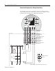
Table Of Contents
- 2727-UM002D-EN-P, MobileView Guard G750 Terminal User Manual
- Important User Information
- Table of Contents
- Preface
- Chapter 1 - Overview
- Chapter 2 - Safety Precautions and Elements
- Chapter 3 - Terminal Connections
- Chapter Objectives
- Mounting and Connecting the Junction Box
- Accessing/Wiring the MobileView Connection Compartment
- Connecting a Computer using the RS-232 Serial Port
- Making an Ethernet Connection
- Using the PC Card Slot
- Connecting a Keyboard / Printer Using the IrDA Interface
- Installing the Mounting Bracket
- Chapter 4 - Configuring the MobileView Terminal
- Chapter 5 - Using RSView ME Station
- Chapter 6 - CE Thin Client Operating Instructions
- Chapter 7 - Windows CE Applications
- Chapter 8 - Maintenance and Troubleshooting
- A - Specifications
- B - Security Considerations
- C - Available Fonts for Terminal Applications
- Index
- Back Cover
Publication 2727-UM002D-EN-P
2-6 Safety Precautions and Elements
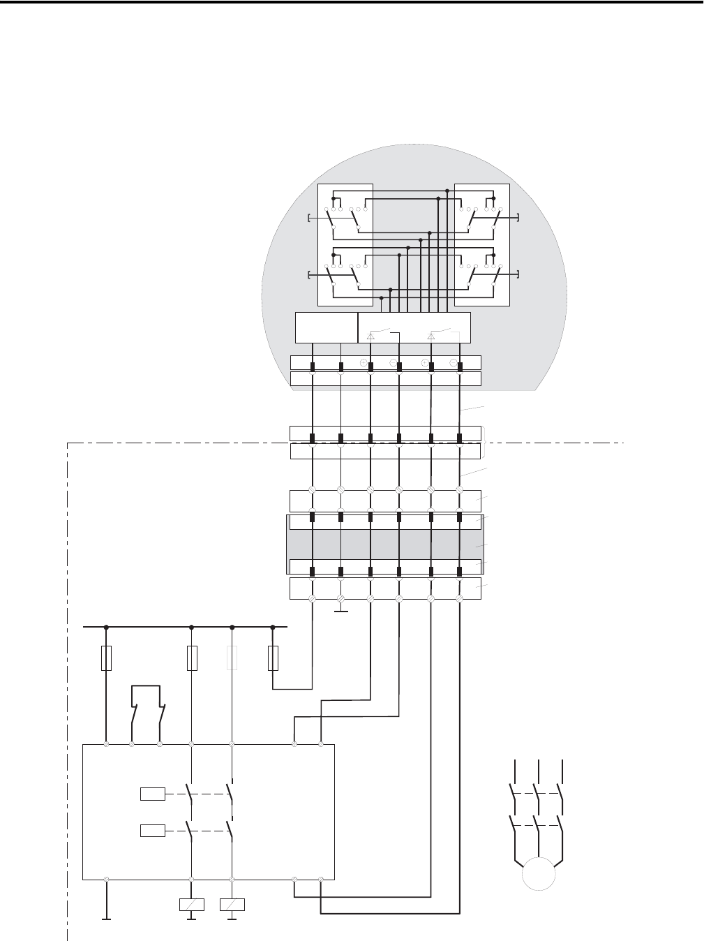
Connection Example with a Safety Control Relay
The diagram below shows suggested wiring for enabling switches
using a PILZ PST safety control relay to meet safety category 3. Refer
to PILZ PST documentation for additional information.
PILZ
PST1
GND
A1(+) 23 S11
A2(-)
13
14 24 S23 S24
KA KB
S12
K1
K2
+24 VDC
F1
1A
F2
4A(t)
or
6A(f)
KA KB
X1 X2
KA
KB
L1 L2 L3
M
F3
4A(t)
or
6A(f)
GND GND
F4
3,15A
GND
12 34
12 34
123 123 321 321
123 123 321 321
ZT1
L
ZT2
L
ZT1
R
ZT2
R
DC/DC
converter
67
67
S19:
K3:
7 8 12 17K1: 1 2
K1:
7 8 12 1712
+24V GND ED1+ ED1- ED2+ ED2-
X1
X2
+24V GND ED1+ ED1- ED2+ ED2-K4:
K3:
Evaluation electronics
C ircuit 1 C ircuit 2
ZTx
y
....... enabling switch x
y
Feedback
control loop
Control cabinet
MobileView
(2 enabling switches with
3 positions and 2 circuits each)
Connection cable
MobileView
17-pin
coinvers jack
Intermediate cable
MobileView
Terminal block socket K3 on
connection box
Male connector X1 on
connection box
Connection box
Male connector X2 on
connection box
Terminal block socket K4 on
connection box
Enabling of dangerous
movement
Note: All contacts of KA and KB must be forced-guided!