
User guide
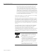
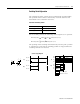
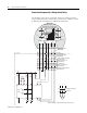
Table Of Contents
- 2727-UM002D-EN-P, MobileView Guard G750 Terminal User Manual
- Important User Information
- Table of Contents
- Preface
- Chapter 1 - Overview
- Chapter 2 - Safety Precautions and Elements
- Chapter 3 - Terminal Connections
- Chapter Objectives
- Mounting and Connecting the Junction Box
- Accessing/Wiring the MobileView Connection Compartment
- Connecting a Computer using the RS-232 Serial Port
- Making an Ethernet Connection
- Using the PC Card Slot
- Connecting a Keyboard / Printer Using the IrDA Interface
- Installing the Mounting Bracket
- Chapter 4 - Configuring the MobileView Terminal
- Chapter 5 - Using RSView ME Station
- Chapter 6 - CE Thin Client Operating Instructions
- Chapter 7 - Windows CE Applications
- Chapter 8 - Maintenance and Troubleshooting
- A - Specifications
- B - Security Considerations
- C - Available Fonts for Terminal Applications
- Index
- Back Cover

Publication 2727-UM002D-EN-P
Safety Precautions and Elements 2-7
• Only if both channels of ZT
L
or ZT
R
are activated
“simultaneously” will both output relays K1 and K2 energize and
the output contacts 13-14 and 23-24 close.
• The output relays K1 and K2 will not energize if:
– only one enabling channel is activated,
– the tolerance value for the simultaneity period is exceeded,
– the feedback control loop X1-X2 is open.
• If one enabling channel is released after being simultaneously
activated, the output relays K1 and K2 will return to their initial
position. The forced-guided output contacts 13-14 and 23-24 will
open. The output relays will only energize again after both
enabling channels have been released and operate
simultaneously again.
In this way, the enabling switches avoid that one single error making
the safety function inoperable. A single error will be recognized at the
next cycle at the latest.
Switching Element Data
The switching elements of the enabling switches are protected against
reversed polarity. The outputs of both circuits are protected against
short circuits and excess load.
• Circuit 1: thermal protective circuit
• Circuit 2: fold back protective circuit
Nominal voltage 24V dc (typical)
32V dc (maximum)
Nominal current 500 mA (typical)
Short-circuit current circuit 1; maximum 1.9 A
circuit 2: maximum 600 mA
Max. inductive load (at 500 mA) circuit 1: >1H
circuit 2: maximum 320 mH
Max. capacitive load circuit 1: no limit since the transistor is
protected thermally
circuit 2: maximum 500 µF