
User guide
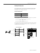
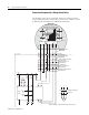
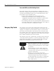
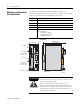
Table Of Contents
- 2727-UM002D-EN-P, MobileView Guard G750 Terminal User Manual
- Important User Information
- Table of Contents
- Preface
- Chapter 1 - Overview
- Chapter 2 - Safety Precautions and Elements
- Chapter 3 - Terminal Connections
- Chapter Objectives
- Mounting and Connecting the Junction Box
- Accessing/Wiring the MobileView Connection Compartment
- Connecting a Computer using the RS-232 Serial Port
- Making an Ethernet Connection
- Using the PC Card Slot
- Connecting a Keyboard / Printer Using the IrDA Interface
- Installing the Mounting Bracket
- Chapter 4 - Configuring the MobileView Terminal
- Chapter 5 - Using RSView ME Station
- Chapter 6 - CE Thin Client Operating Instructions
- Chapter 7 - Windows CE Applications
- Chapter 8 - Maintenance and Troubleshooting
- A - Specifications
- B - Security Considerations
- C - Available Fonts for Terminal Applications
- Index
- Back Cover
Publication 2727-UM002D-EN-P
3-2 Terminal Connections
Mounting and Connecting
the Junction Box
The MobileView Junction Box (2727-MRJB1) integrates the
MobileView terminal into the control system. It mounts on a DIN rail
inside an enclosure and has the following connectors:
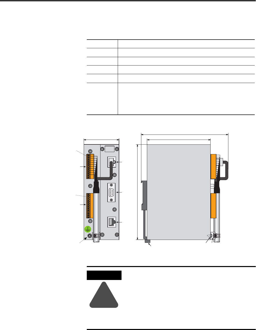
Connectors Description
S1 RJ-45 jack for connecting the MobileView data lines.
S2 9-pin DSUB female connector (for future use).
S3 RJ-45 jack to Ethernet network.
X1 12-pin male connector for connecting the Junction Box Cable.
X2 12-pin male connector (shipped with a female terminal block connector)
for connecting the:
• 24V dc power supply
• emergency stop switch
• enabling switches
24V DC
ON LY
TER M INAL IN
R S422 OUT
ETHERNET OUT
+24V
GND
ES1+
ES1-
ES2+
ES2-
ED1+
ED1-
ED2+
ED2-
+24V
GND
ES1+
ES1-
ES2+
ES2-
ED1+
ED1-
ED2+
ED2-
X2
(with Female
Terminal Block
Connector K4)
S1
S2
S3
Junction Box
Pin 1, 24V dc
Pin 1, 24V dc
162 mm (6.4 in.)
X1
(with Female
Terminal Block
Connector K3)
108 mm (4.25 in)
150 mm (5.91 in)
60 mm (2.36 in)
DIN Rail Latch
Grounding Screw
Strain Relief
for Cable
Grounding Screw
ATTENTION
!
The MobileView Junction Box and the MobileView
terminal meet the safety class III in accordance with
EN 61131-2 and EN 50178.
When connecting the terminal, make sure all
voltages connected to the MobileView terminal are
safety extra low voltages and isolated from the low
voltage supply system by a safety transformer or a
similar safety component.