
User guide
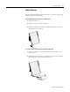
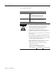
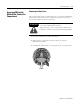
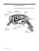
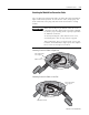
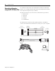
Table Of Contents
- 2727-UM002D-EN-P, MobileView Guard G750 Terminal User Manual
- Important User Information
- Table of Contents
- Preface
- Chapter 1 - Overview
- Chapter 2 - Safety Precautions and Elements
- Chapter 3 - Terminal Connections
- Chapter Objectives
- Mounting and Connecting the Junction Box
- Accessing/Wiring the MobileView Connection Compartment
- Connecting a Computer using the RS-232 Serial Port
- Making an Ethernet Connection
- Using the PC Card Slot
- Connecting a Keyboard / Printer Using the IrDA Interface
- Installing the Mounting Bracket
- Chapter 4 - Configuring the MobileView Terminal
- Chapter 5 - Using RSView ME Station
- Chapter 6 - CE Thin Client Operating Instructions
- Chapter 7 - Windows CE Applications
- Chapter 8 - Maintenance and Troubleshooting
- A - Specifications
- B - Security Considerations
- C - Available Fonts for Terminal Applications
- Index
- Back Cover
Publication 2727-UM002D-EN-P
Terminal Connections 3-9
Accessing/Wiring the
MobileView Connection
Compartment
Removing the Back Cover
This section shows how to remove the back cover of the MobileView
terminal. Once the back cover is removed, you have access to the
area which contains all of the connectors.
1. Place the terminal on a stable, flat surface.
2. Remove the 6 screws that secure the back cover to the
MobileView terminal.
3. Carefully lift off the back cover and place it on a secure surface.
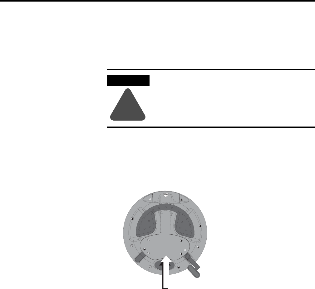
ATTENTION
!
Turn off the power supply before removing the back
cover of the MobileView terminal.
When the back cover is removed, the MobileView
terminal is sensitive to electrostatic discharge (ESD).
Back Cover