
User guide
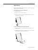
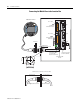
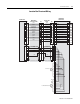
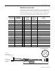
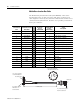
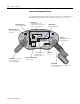
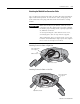
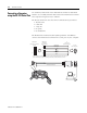
Table Of Contents
- 2727-UM002D-EN-P, MobileView Guard G750 Terminal User Manual
- Important User Information
- Table of Contents
- Preface
- Chapter 1 - Overview
- Chapter 2 - Safety Precautions and Elements
- Chapter 3 - Terminal Connections
- Chapter Objectives
- Mounting and Connecting the Junction Box
- Accessing/Wiring the MobileView Connection Compartment
- Connecting a Computer using the RS-232 Serial Port
- Making an Ethernet Connection
- Using the PC Card Slot
- Connecting a Keyboard / Printer Using the IrDA Interface
- Installing the Mounting Bracket
- Chapter 4 - Configuring the MobileView Terminal
- Chapter 5 - Using RSView ME Station
- Chapter 6 - CE Thin Client Operating Instructions
- Chapter 7 - Windows CE Applications
- Chapter 8 - Maintenance and Troubleshooting
- A - Specifications
- B - Security Considerations
- C - Available Fonts for Terminal Applications
- Index
- Back Cover
Publication 2727-UM002D-EN-P
3-10 Terminal Connections
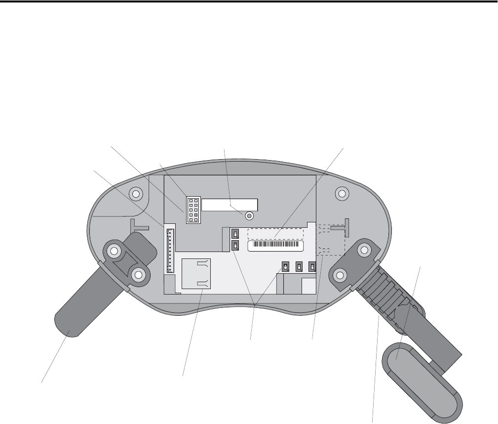
Connection Compartment Details
The following illustration shows what the connection compartment of
the MobileView terminal looks like with the back cover removed.
Ethernet
B5
B4
B2 B6 B3
Serial
port
R eset
S6,
COM -Modul
AABBCCDDEEFF
00:60:B5:06:00:01
2250-00001
Ethernet
B5
B4
B2 B6 B3
Serial
port
R eset
S6,
COM -Modul
AABBCCDDEEFF
00:60:B5:06:00:01
2250-00001
RS-232 Serial Port
for downloading software.
Reset Button
for rebooting Windows CE.
All data not flushed to Registry or
saved to Flash Storage is lost.
Important: Install plug on the
unused MobileView
Connection Cable outlet.
Main connector (S19)
for power supply and
control lines
Ethernet connector (S4)
for data exchange
Connector
not used
Strain Relief
for connecting MobileView Connection Cable
(on left or right side)
Ethernet label
Ethernet (MAC) address
Cable Tag
allows the terminal to be
uniquely identified.
Pin 1
Position of switches does
not affect terminal
operation (for future use)
S19
S4