
User guide
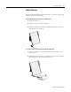
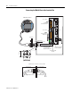
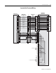
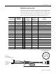
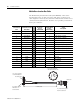
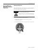
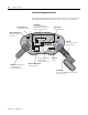
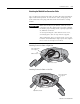
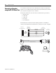
Table Of Contents
- 2727-UM002D-EN-P, MobileView Guard G750 Terminal User Manual
- Important User Information
- Table of Contents
- Preface
- Chapter 1 - Overview
- Chapter 2 - Safety Precautions and Elements
- Chapter 3 - Terminal Connections
- Chapter Objectives
- Mounting and Connecting the Junction Box
- Accessing/Wiring the MobileView Connection Compartment
- Connecting a Computer using the RS-232 Serial Port
- Making an Ethernet Connection
- Using the PC Card Slot
- Connecting a Keyboard / Printer Using the IrDA Interface
- Installing the Mounting Bracket
- Chapter 4 - Configuring the MobileView Terminal
- Chapter 5 - Using RSView ME Station
- Chapter 6 - CE Thin Client Operating Instructions
- Chapter 7 - Windows CE Applications
- Chapter 8 - Maintenance and Troubleshooting
- A - Specifications
- B - Security Considerations
- C - Available Fonts for Terminal Applications
- Index
- Back Cover
Publication 2727-UM002D-EN-P
Terminal Connections 3-11
Attaching the MobileView Connection Cable
You can attach the Connection Cable on either side of the terminal for
right or left-hand operation. To relocate the cable, simply grasp the
strain relief and/or the plug and slide off of mount with a rocking
motion.
Attaching Connection Cable on Right Side
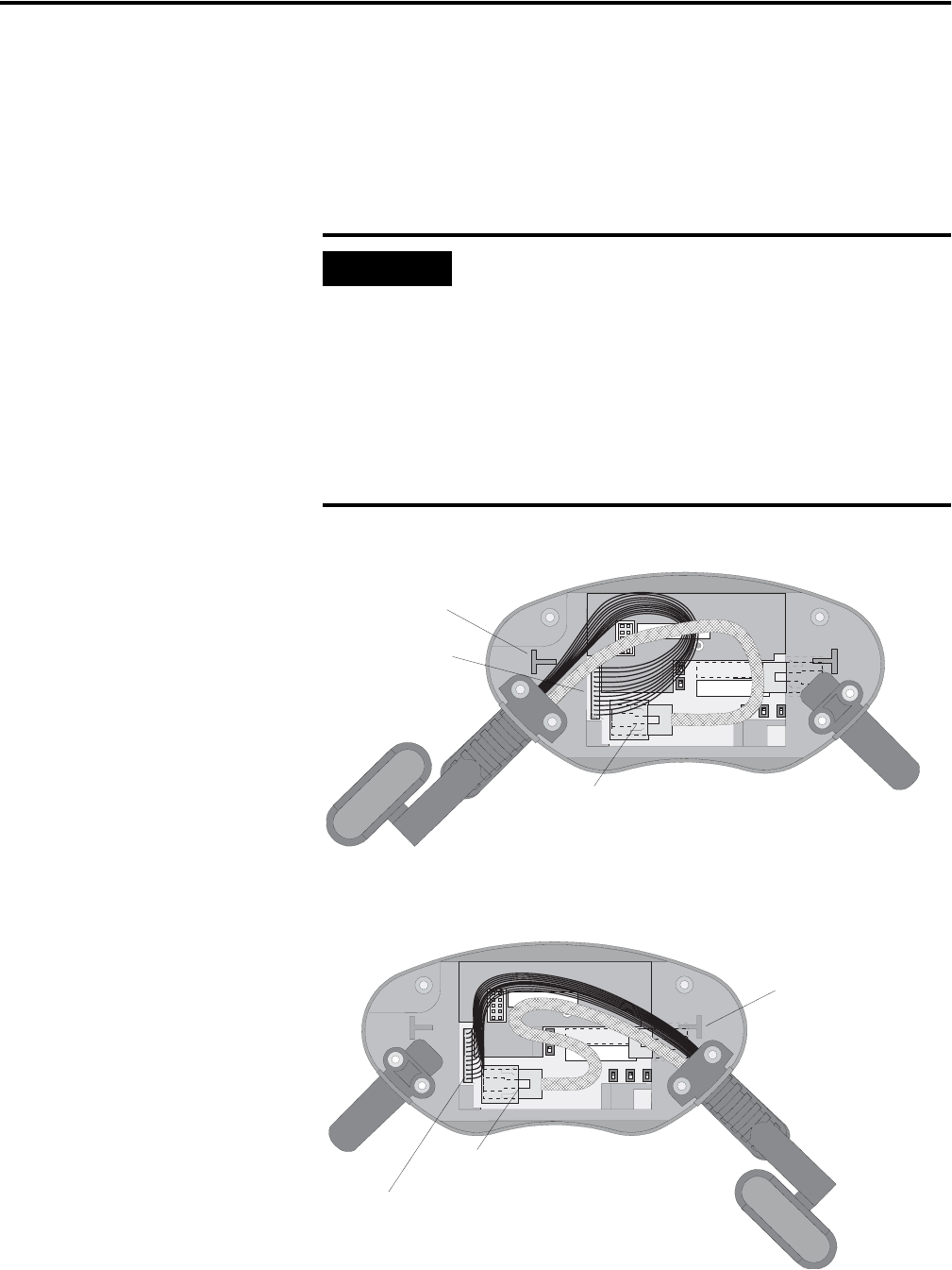
Attaching Connection Cable on Left Side
IMPORTANT
Make sure the K3, 11-pin female connector clicks
completely into S19, Main Connector when plugged
in. Ensure proper seating of K2, 8-pin RJ-45 jack into
S4, Ethernet Connector.
To avoid pinching the cable with the back cover,
avoid laying the cable on top of the T-supports.
After routing the cable, secure the back cover to the
terminal. To maintain IP54 degree protection, tighten
the 6 screws to a torque of 4.42 in-lb.
S6,
COM -M odul
S19
Main Connector
S4, Ethernet Connector
Avoid routing cable
over T-support.
S6,
COM -M odul
S19, Main Connector
S4, Ethernet Connector
Avoid routing cable
over T-support.