
User guide
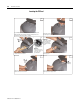
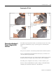
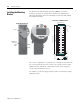
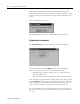
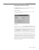
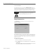
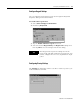
Table Of Contents
- 2727-UM002D-EN-P, MobileView Guard G750 Terminal User Manual
- Important User Information
- Table of Contents
- Preface
- Chapter 1 - Overview
- Chapter 2 - Safety Precautions and Elements
- Chapter 3 - Terminal Connections
- Chapter Objectives
- Mounting and Connecting the Junction Box
- Accessing/Wiring the MobileView Connection Compartment
- Connecting a Computer using the RS-232 Serial Port
- Making an Ethernet Connection
- Using the PC Card Slot
- Connecting a Keyboard / Printer Using the IrDA Interface
- Installing the Mounting Bracket
- Chapter 4 - Configuring the MobileView Terminal
- Chapter 5 - Using RSView ME Station
- Chapter 6 - CE Thin Client Operating Instructions
- Chapter 7 - Windows CE Applications
- Chapter 8 - Maintenance and Troubleshooting
- A - Specifications
- B - Security Considerations
- C - Available Fonts for Terminal Applications
- Index
- Back Cover
Publication 2727-UM002D-EN-P
3-14 Terminal Connections
Inserting the PC Card
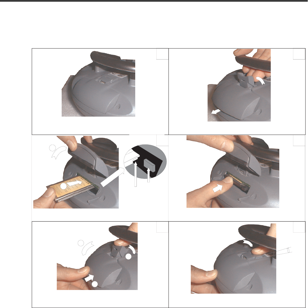
Lay the MobileView with the display facing down onto a flat, clean
table, preferably on Electrostatic Discharge (ESD) pad. Take care
not to damage the terminal and its elements.
Unlock the PC card cover as shown (until
the locking lever is released)
1. Open the cover.
2. Insert the PC card as shown.
Ejection button
Attention:
Verify that this corner
is inserted into the slot
on the side of the
ejection button.
1
2
3
4
5
6
Insert the PC card until it locks in and the ejection
button pops out.
1. Close the cover.
2. and 3. Lock the cover as shown.
Press down the cover until it snaps in completely to
meet the protection degree IP54.
Must snap
completely.
1
2
3
1
2
Attention:
Check the condition
and position of the
cover seal before
closing the PC card
cover.