
User guide
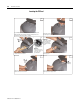
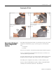
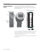
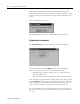
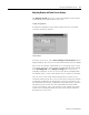
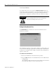
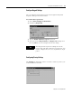
Table Of Contents
- 2727-UM002D-EN-P, MobileView Guard G750 Terminal User Manual
- Important User Information
- Table of Contents
- Preface
- Chapter 1 - Overview
- Chapter 2 - Safety Precautions and Elements
- Chapter 3 - Terminal Connections
- Chapter Objectives
- Mounting and Connecting the Junction Box
- Accessing/Wiring the MobileView Connection Compartment
- Connecting a Computer using the RS-232 Serial Port
- Making an Ethernet Connection
- Using the PC Card Slot
- Connecting a Keyboard / Printer Using the IrDA Interface
- Installing the Mounting Bracket
- Chapter 4 - Configuring the MobileView Terminal
- Chapter 5 - Using RSView ME Station
- Chapter 6 - CE Thin Client Operating Instructions
- Chapter 7 - Windows CE Applications
- Chapter 8 - Maintenance and Troubleshooting
- A - Specifications
- B - Security Considerations
- C - Available Fonts for Terminal Applications
- Index
- Back Cover
Publication 2727-UM002D-EN-P
Terminal Connections 3-15
Removing the PC Card
Connecting a Keyboard /
Printer Using the IrDA
Interface
The IrDA keyboard/printer interface is built into the lower rim of the
MobileView terminal (see page
1-3) and supports communication
with:
• keyboards
• printers
The port is located for convenient operation with an IrDA keyboard.
To use a standard PC keyboard with the IrDA port, you must use a
converter (PS2 keypad to IrDA).
To print using the IrDA port, you must orient the MobileView towards
the IrDA port of the printer. The printer must be PCL compatible.
The IrDA port is assigned to the COM 3 or COM 4 interface port.
Protocol: Only the HP-SIR (Low Speed) coding is used (LPM Mode
enabled). The maximum baud rate is 115.2K baud.
Unlock the PC card cover as shown
(until the locking lever is released).
Press down the cover until it snaps in completely to meet
the protection degree IP54.
1. Open the PC card cover.
2. Press the ejection button of the PC card slot.
3. Remove the PC Card
1. Close the cover.
2. and 3. Lock the cover as shown.
1
2
3
4
1
2
3
1
3
2
Must
snap
completely.