
User guide
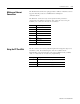
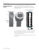
Table Of Contents
- 2727-UM002D-EN-P, MobileView Guard G750 Terminal User Manual
- Important User Information
- Table of Contents
- Preface
- Chapter 1 - Overview
- Chapter 2 - Safety Precautions and Elements
- Chapter 3 - Terminal Connections
- Chapter Objectives
- Mounting and Connecting the Junction Box
- Accessing/Wiring the MobileView Connection Compartment
- Connecting a Computer using the RS-232 Serial Port
- Making an Ethernet Connection
- Using the PC Card Slot
- Connecting a Keyboard / Printer Using the IrDA Interface
- Installing the Mounting Bracket
- Chapter 4 - Configuring the MobileView Terminal
- Chapter 5 - Using RSView ME Station
- Chapter 6 - CE Thin Client Operating Instructions
- Chapter 7 - Windows CE Applications
- Chapter 8 - Maintenance and Troubleshooting
- A - Specifications
- B - Security Considerations
- C - Available Fonts for Terminal Applications
- Index
- Back Cover
Publication 2727-UM002D-EN-P
3-16 Terminal Connections
Installing the Mounting
Bracket
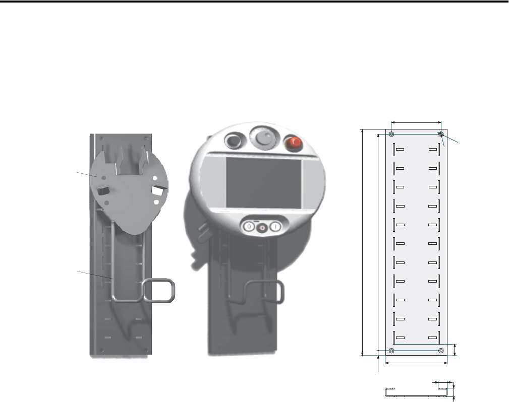
The MobileView Mounting Bracket (2727-MRMB1) is used for
stationary operation or storage of the MobileView terminal. The
following illustration shows the mounting bracket with and without
the terminal mounted.
The carrier is adjustable in 8 positions over a height of 320 mm (12.60
in). It is important to attach the carrier at all 4 points on the height
adjustment plate. Mount the cable holder on the carrier using the
screws shipped with the bracket.
Use suitable screws (not shipped with product) to mount the height
adjustment plate.
Carrier
MobileView
Connection
Cable
Holder
120 mm (4.72 in)
526 mm (20.71 in)
550 mm (21.65 in)
6
m
m
d
i
a
.
(
0
.
2
4
i
n
)
1
2
m
m
d
i
a
.
(
0
.
4
7
i
n
)
12 mm (0.47 in)
150 mm (5.91 in)
28 mm
(1.1 in)
22 mm (0.87 in)
20 mm
(0.79 in)
Height Adjustment Plate
Dimensions and Mounting Holes