
User guide
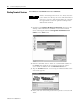

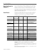
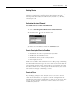
Table Of Contents
- 2727-UM002D-EN-P, MobileView Guard G750 Terminal User Manual
- Important User Information
- Table of Contents
- Preface
- Chapter 1 - Overview
- Chapter 2 - Safety Precautions and Elements
- Chapter 3 - Terminal Connections
- Chapter Objectives
- Mounting and Connecting the Junction Box
- Accessing/Wiring the MobileView Connection Compartment
- Connecting a Computer using the RS-232 Serial Port
- Making an Ethernet Connection
- Using the PC Card Slot
- Connecting a Keyboard / Printer Using the IrDA Interface
- Installing the Mounting Bracket
- Chapter 4 - Configuring the MobileView Terminal
- Chapter 5 - Using RSView ME Station
- Chapter 6 - CE Thin Client Operating Instructions
- Chapter 7 - Windows CE Applications
- Chapter 8 - Maintenance and Troubleshooting
- A - Specifications
- B - Security Considerations
- C - Available Fonts for Terminal Applications
- Index
- Back Cover

Publication 2727-UM002D-EN-P
7-2 Windows CE Applications
Generating Programs for
Windows CE
You can easily generate programs for Windows CE. Programming is
similar to an application for a standard MS Windows NT PC. Under
Windows CE, only the number of available WIN32-APIs is limited.
Two Software Developers Kit SDK are included in on the product CD:
Virtual Channel SDK and CE 4.x SDK. The User Manual for the CE 4.x
SDK is located on the product CD.
Virtual Channel
The protocol "Virtual Channel" (VC) is used to transmit control and
operating element data between a controller (control application
running on a server) and one or more MobileView terminals.
The following data can be transmitted via the VC:
Data transmission between the controller and MobileView terminal is
based on the Ethernet connection (TCP/IP protocol, Listening Port
0xCEBA). All devices must be identified by their IP address.
Several MobileView terminals may be connected to one controller, but
only one controller can be connected to a MobileView terminal at any
given time.
The VC protocol is an event-driven protocol, i.e. each station can send
data at any time without request.
Data Direction
Server <--> MT
Value Range Size (Bytes) Transmission
Potentiometer <-- 0 to 127 1 Event in case of modification and
upon request of the control
Electrical handwheel <--> -32768 to +32768 2 Event in case of modification, upon
request of the control, and as set
command for adjusting
Enable Switch <-- 0/1 1 Event in case of modification
Keys/buttons below
display
Push button LEDS <--> On
Flashing
Off
2 As command from the control and as
request from the client to the control.
Contrast, Brightness <--> 0 to 255 2 As command from the control and as
request from the client to the control.
Time for Screen Saver <--> 0 to 255 1 As command from the control and as
a request from the client to the
control.
State of Screen Saver <--> 0 to 1 1 Event or as request from the client to
the control.
Volume <--> 0 to 255 1 As command from the control and as
request from the client to the control.
Background Lighting <--> 0 to 1 1 As command from the control and as
request from the client to the control.
WriteToFlash --> - - Command
PlaySound --> 0 to 255 1 Command
KeepAlive <--> 0 to 65535 - Command