QUICK START ARMORSTART® DISTRIBUTED MOTOR CONTROLLER WITH ARMORPOINT® BACKPLANE Getting Started BULLETIN 283A Introduction This guide provides the basic information required to start up your ArmorStart® Distributed Motor Controller. Factory default settings and information regarding installing, programming, and ArmorPoint® Communication Backplane, are described here. For detailed information on specific product features or configurations, refer to the ArmorStart user manual, Publication 283-UM001*-EN-P.
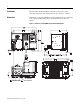
Installation The ArmorStart Distributed Motor Controller is convection cooled. Operating temperature must be kept between -20…40°C (-4…104°F). Dimensions Dimensions are shown in millimeters (inches). Dimensions are not intended to be used for manufacturing purposes. All dimensions are subject to change.
Dimensions are shown in millimeters (inches). Dimensions are not intended to be used for manufacturing purposes. All dimensions are subject to change.
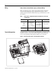
Wiring Power, Control, Safety Monitor Inputs, and Ground Wiring Table 1 provides the power, control, safety monitor inputs, ground wire capacity and the tightening torque requirements. The power, control, ground, and safety monitor terminals will accept a maximum of two wires per terminal. Table 1 Terminal Designations Power, Control, Safety Monitor Inputs, Ground Wire Size, and Torque Specifications Terminals Wire Size Torque Wire Strip Length Power and Ground Primary/Secondary Terminal: 1.0…4.
Table 2 Power, Control, and Ground Terminal Designations Terminal Designations No. of Poles Description SM1 ➊ SM2 ➊ A1 (+) A2 (-) PE 1/L1 3/L3 5/L5 2 2 2 2 2 2 2 2 Safety Monitor Input Safety Monitor Input Control Power Input Control Power Common Ground Line Power Phase A Line Power Phase B Line Power Phase C ➊ Only available with the Safety Monitor option.
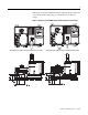
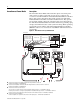
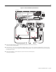
ArmorConnect Power Media Description The ArmorStart Power Media offers both three-phase and control power cable system of cordsets, patchcords, receptacles, tees, reducers and accessories to be utilized with the ArmorStart Distributed Motor Controller. These cable system components allow quick connection of ArmorStart Distributed Motor Controllers and reduce installation time.
Figure 5 Control Power Media System Overview Enclosure PLC Bulletin 1492FB Branch Circuit Protective Device Computer Terminal Bulletin 1606 Bulletin 1606 8 Ethernet Bulletin 283 ArmorStart Bulletin 284 ArmorStart ArmorPoint 6 6 Bulletin 800F Emergency Stop Pushbutton 6 6 7 7 ➏ Control Power Media Patchcords - PatchCord cable with integral female or male connector on each end Example Part Number: 889N-F65GFNM-* ➐ Control Power Tees - The E-stop In Tee (Part Number: 898N-653ES-NKF) is used to
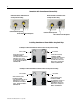
ArmorStart with ArmorConnect Connectivity ArmorStart devices with 25 A short circuit protection rating ArmorStart devices with 10 A short circuit protection rating Control Power Receptacle Three-Phase Power Receptacle Control Power Receptacle Three-Phase Power Receptacle Installing ArmorConnect Power Media using Cord Grips Cord Grips for ArmorStart Devices with 10 A short circuit protection rating 3/4 in. Lock Nut Thomas & Betts Cord Grip Part Number: 2931NM 3/4 in.
Terminal Designations Description Color Code A1 (+) Control Power Input Blue A2 (-) Control Power Common Black PE Ground Green/Yellow 1/L1 Line Power - Phase A Black 2/L2 Line Power - Phase B White 3/L3 Line Power - Phase C Red ArmorConnect Cable Ratings The ArmorConnect Power Media cables are rated per UL Type TC 600V 90 °C Dry 75 °C Wet, Exposed Run (ER) or MTW 600V 90 °C or STOOW 105 °C 600V - CSA STOOW 600V FT2.
Group Motor Installations for USA and Canada Markets The ArmorStart Distributed Motor controllers are listed for use with each other in group installations per NFPA 79, Electrical Standard for Industrial Machinery. When applied according to the group motor installation requirements, two or more motors, of any rating or controller type, are permitted on a single branch circuit. Group Motor Installation has been successfully used for many years in the USA and Canada.
The working space around the ArmorStart may be minimized as the ArmorStart does not require examination, adjustment, servicing or maintenance while energized. In lieu of this service, the ArmorStart is meant to be unplugged and replaced after proper lockout/tag-out procedures have been employed.
LED Status Indication The LED Status Indication provides 4 status LEDs and a Reset button.
ArmorStart with ArmorPoint ArmorStart for the ArmorPoint Backplane The Bulletin 283A ArmorStart Distributed Motor Controller allows connectivity to the ArmorPoint backplane. The ArmorPoint I/O system can communicate using DeviceNet™, ControlNet™, or EtherNet communication protocols. In addition to the other network communication protocols; the ArmorPoint Distributed I/O products allow the I/O capability to be expanded beyond the standard two outputs.
ArmorPoint Backplane Commissioning Establishing a Backplane Node Address Backplane node addresses are established automatically by the ArmorPoint system on power up. Node addresses for the backplane modules are allocated from left to right, starting at address 1. Note: The rotary address switches on the starter module are ignored when using the ArmorPoint backplane.
is a flag word that tells the ladder logic if the parameter is read only. If the read only bit is set, then the ladder logic will skip the additional attribute reads and will go to the next parameter. If the parameter is writable, then the logic will read the size, min. allowed value, max. allowed value, the parameter name, help string and the raw data of each parameter. These attributes are stored in the data array for use later when the configuration is written to each ArmorStart.
The only configuration that the user needs to be concerned with for the ArmorPoint communication adapter is either the EtherNet IP address or the ControlNet node address. Since there currently is no profile for an ArmorStart device in the I\O Tree, the 1738-MODULE profile needs to be used as a generic profile. The standard configuration for an ArmorStart 283A, using this profile is shown below.
Shown below is the array size that will also need to be changed to match the Armor_Start_System.Max_Devices value. Figure 12 System Array Size Armor_Start_System.Max_Parameters defaults to 262, because the maximum number of parameters in any existing ArmorStart product is 262 or less. This amount can be easily be changed, and doing so will also proportionally change the size of the System Array structure and the Logix memory that holds it.
Adding Devices to the Configuration Structure Once the three major System level parameters are entered, it is up to the user to enter in, each of the ArmorStart devices configuration information. These parameters are defined by the slot in the Logix chassis where the EtherNetIP or ControlNet communication card resides. The next parameter is the EtherNetIP IP or ControlNet node address of the 1738 communication adapter containing the ArmorStart.
Click on the three dots icon and a String Browser box appears. Modify the text to what is desired and click on Apply, then click on OK. This works for ALL strings throughout the entire data array. Figure 16 String Browser Box Modifying Parameter Data for an ArmorStart The last configuration that will need to be done eventually, is the writing of a parameter configuration change for an ArmorStart. This is done by first equating a particular ArmorStart to a device number in the data array.
Figure 17 Data Array The value to be modified is the .data element of the structure. For reference, the Min_value, Max_value, and Name_String for the parameter is also in the structure, so that the user knows what the minimum and maximum allowable values are for the data. It is important to realize that the data is in a raw format. In other words, this data could be considered a Boolean, a bit mask, an ASCII string, an integer, a byte, etc.
Triggering a System Wide Read Once the system configuration has been done, a System Wide Read must be initiated. The logic to trigger both a System Wide Read and Write is contained in a subroutine called Handle_All_Armor. The rungs are shown below for reference. Figure 18 Handle_All_Armor Rungs To trigger the system wide read, the contact Read_All_Condition_Here needs to be energized in the ladder logic.
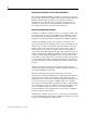
Interpreting the Error Report If an error occurs during the operation of the ladder logic, either the Write_All_System_Error_Flag or Read_All_System_Error_Flag bits will energize depending on which function was being triggered. Information will be logged inside the data structure Error_Report, that will aid in troubleshooting the problem. The format of this structure is shown below. Figure 19 Error Report The first element of this structure is .
Quick Reference Troubleshooting There are four LEDs on the front of the ArmorStart that can provide an indication as to the health of the device. The following is a brief explanation of the operation of each LED. Table 4 LED Status Indication LED Definition Power This LED will be illuminated solid green when control power is present and with the correct polarity. Run This LED will be illuminated solid green when a start command and control power are present.
Fault LED indications for Bulletin 283A ArmorStart Distributed Motor Controllers Table 6 Blink Pattern Controller Fault LED Definitions Definitions Possible Causes or Remedies Short Circuit The motor circuit protector has tripped, or the internal wiring protection algorithm has detected an unsafe current range. Try to reset the protector if tripped. If the condition continues, check the power wiring. This fault cannot be disabled.
Bulletin 283 Parameters Table 7 Starter Display and Parameter Settings Parameter Name String Path (hex) Min Max Dflt Type Value 101 102 103 104 105 Phase A Current Phase B Current Phase C Current Average Current % Therm Utilized 002C – 01 – 08 002C – 01 – 09 002C – 01 – 0A 002C – 01 – 05 002C – 01 – 07 32767 32767 32767 32767 100 — — — — — INT INT INT INT USINT xxx.x Amps xxx.x Amps xxx.x Amps xxx.
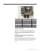
Figure 20 Bulletin 283 ArmorStart Local Disconnect LED Status Indication 2 Outputs (Micro/M12) ArmorPoint Interface (IN) Source Brake Connector Motor Connection ArmorPoint Interface (OUT) Ground Terminal Figure 21 Bulletin 283 ArmorStart with ArmorConnect Control Power Three-Phase Power Ground Terminal Publication 283A-QS001C-EN-P - July 2006 Control Power Three-Phase Power Ground Terminal
Table 9 DeviceNet Media ➊ Description Length m (ft) Cat. No. Sealed KwikLink pigtail drops are Insulation Displacement Connector (IDC) with integral Class 1 round cables for interfacing devices or power supplies to flat cable 1 m (3.3) 1485P-P1E4-B1-N5 2 m (6.5) 1485P-P1E4-B2-N5 3 m (9.8) 1485P-P1E4-B3-N5 6 m (19.8) 1485P-P1E4-B6-N5 Right Keyway Left Keyway 1485P-P1N5-MN5NF 1485P-P1N5-MN5KM Connector Cat. No.
Table 10 Sensor Media ➊ ArmorStart I/O Connection Description Pin Count Connector Cat. No.
Bulletin 1738 ArmorPoint Distributed I/O Products Table 13 Digital I/O Products Description 0 Cat. No. 24V DC 8 Source Output w/ 8 M12 connectors 1738-OB8EM12 24V DC 8 Source Output w/ 8 M8 connectors 1738-OB8EM8 24V DC 4 Source Output w/ 4 M12 connectors 1738-OB4EM12 24V DC 4 Source Output w/ 4 M8 connectors 1738-OB4EM8 24V DC 2 Source Output w/ 2 M12 connectors 1738-OB2EM12 24V DC 2 Source Output - 2 A Prot.
Table 17 AC and Relay Products Description 0 Cat. No. 24V DC Coil N.O. DPST Relay w/ 2 M12 connectors 1738-OW4M12 24V DC Coil N.O. DPST Relay w/ 2 AC M12 connectors 1738-OW4M12AC4 120V AC 2 Input w/ 2 AC 4 pin M12 connectors 1738-IA2M12AC4 120V AC 2 Input w/ 2 AC 3 pin M12 connectors 1738-IA2M12AC3 120/230V AC 2 Output w/ 2 AC 3 pin M12 connectors 1738-OA2M12AC3 Table 18 Specialty Products Description 0 Cat. No.
Notes: Publication 283A-QS001C-EN-P - July 2006
Registered Trademark List ArmorPoint and ArmorStart are registered trademarks of Rockwell Automation, Inc. Trademark List ArmorConnect, RSLogix5000, PLC, RSNetWorx, and SLC are trademarks of Rockwell Automation, Inc. ControlNet is a trademark of ControlNet International, LTD. DeviceNet and the DeviceNet logo are trademarks of the Open Device Vendors Association (ODVA).