
Getting Started User Manual

Publication 283A-QS001C-EN-P - July 2006
25
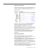
Bulletin 283 Parameters
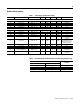
Table 7 Starter Display and Parameter Settings
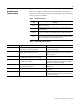
Table 8 FLA Setting Ranges and Default Values (with indicated setting precision)
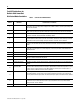
Parameter Name String Path (hex) Min Max Dflt Type Value
SMC Display
101 Phase A Current 002C – 01 – 08 0 32767 — INT xxx.x Amps
102 Phase B Current 002C – 01 – 09 0 32767 — INT xxx.x Amps
103 Phase C Current 002C – 01 – 0A 0 32767 — INT xxx.x Amps
104 Average Current 002C – 01 – 05 0 32767 — INT xxx.x Amps
105 % Therm Utilized 002C – 01 – 07 0 100 — USINT xxx %
SMC Settings
106 FLA Setting 002C – 01 – 03 See Table 8 below Min I INT xxx.x Amps
107 OL Trip Class 002C – 01 – 04 0 3 1 BYTE 1 = 10
108 OL Reset Level 0029 – 01 – 131 0 100 75 BYTE xxx %
109 Start Time 000F - 06D - 01 1 45 10 USINT sec
110 Start Mode 000F - 06E - 01 0 1 0 BOOL
0 = Current Limit
1 = Soft Start
111 Current Limit 000F - 06 - 01 150 600 350 UINT
xxx % FLA
Display multiplier of 10.
SMC is looking for values
between 15 and 60.
112 Initial Torque 000F - 070 - 01 0 90 60 USINT % LRT
113 Soft Stop Time 000F - 071 - 01 0 90 0 USINT sec
114 Kick Start 000F - 072 - 01 0.0 1.5 0.0 USINT sec
115 SCR Temp Reset Mode 000F - 073 - 01 0 1 0 BOOL
0 = Manual
1 = Auto Reset
116 Phase Rotation 000F - 074 - 01 0 1 0 BOOL
0 = Disable
1 = Enable
FLA Current Range (A)
Default Value
Minimum Value Maximum Value
1.1 3.0 1.1
3.0 5.5 3.0
5.3 7.6 5.3
6.3 16.0 6.3