
User Manual Owner's manual


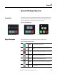
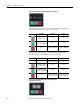
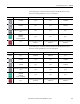
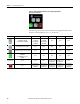
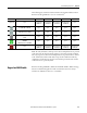

Table Of Contents
- ArmorStart Distributed Motor Controller with EtherNet/IP User Manual
- European Communities (EC) Directive Compliance
- Table of Contents
- Chapter 1
- Product Overview
- Introduction
- Description
- Catalog Number Explanation
- Operation
- Mode of Operation
- Description of Features
- Embedded Switch Technology
- Switched vs. Unswitched Control Power Input/Output (I/O) Connections
- EtherNet/IP™ Ports
- Embedded Web Server
- EtherNet/IP LED Status Indication
- Control Module LED Status and Reset
- Electronic Data Sheet (EDS)
- Fault Diagnostics
- Standard Features
- Factory-Installed Options
- Optional HOA Keypad Configuration (Bulletin 280E/281E only)
- Optional HOA Selector Keypad with Jog Function (Bulletin 284E only)
- Source Brake Contactor and Connector (Bulletin 284E only)
- EMI Filter (Bulletin 284E only)
- Dynamic Brake Connector (Bulletin 284E only)
- IP67 Dynamic Brake Resistor (Bulletin 284E only)
- Output Contactor (Bulletin 284E only)
- Shielded Motor Cable (Bulletin 284E only)
- ArmorStart® EtherNet/ IP Features
- Notes:
- Product Overview
- Chapter 2
- Installation and Wiring
- Receiving
- Unpacking
- Inspecting
- Storing
- General Precautions
- Precautions for Bulletin 280E/281E Applications
- Precautions for Bulletin 284E Applications
- Dimensions
- Mount Orientation
- Operation
- Wiring
- Terminal Designations
- Control Power Wiring
- ArmorStart with EtherNet/IP Internal Wiring
- AC Supply Considerations for Bulletin 284E Units
- Electromagnetic Compatibility (EMC)
- Grounding
- ArmorConnect Power Media
- ArmorConnect Connections
- ArmorConnect Cable Ratings
- Ethernet and I/O Connections
- Power Connections
- Optional Locking Clip
- Installation and Wiring
- Chapter 3
- Chapter 4
- Chapter 5
- Chapter 6
- Chapter 7
- Bulletin 280E/281E/284E Programmable Parameters
- Basic Setup Parameters
- Parameter Groups
- ArmorStart EtherNet/IP Parameters
- Bulletin 280E/281E
- Bulletin 284E
- Basic Status Group
- Produced Assembly Config Group
- Starter Protection Group
- User I/O Configuration Group
- Miscellaneous Configuration Group
- Drive I/O Configuration Group (Bulletin 284E only)
- Drive Display Group (Bulletin 284E only)
- Drive Setup Group (Bulletin 284E only)
- Drive Advanced Setup Group (Bulletin 284E only)
- Clear a Type 1 Fault and Restart the Drive
- Clear an Overvoltage, Undervoltage, or Heatsink OvrTmp Fault without Restarting the Drive
- How StepLogic Works
- StepLogic Settings
- Linear List of Parameters for Bulletin 280E/281E and Bulletin 284E
- Bulletin 280E/281E/284E Programmable Parameters
- Chapter 8
- Chapter 9
- Chapter 10
- Chapter 11
- Chapter 12
- Appendix A
- Applying More Than One ArmorStart Motor Controller in a Single Branch Circuit on Industrial Machinery
- Introduction
- ArmorStart LT Product Family
- Multiple-Motor Branch Circuits and Motor Controllers Listed for Group Installation – General
- Maximum Fuse Ampere Rating According to 7.2.10.4(1) and 7.2.10.4(2)
- Explanatory Example
- Input and Output Conductors of Bulletin 290E and 291E Controllers (a)
- Input and Output Conductors of Bulletin 294E Controllers (b)
- Combined Load Conductors (c)
- Applying More Than One ArmorStart Motor Controller in a Single Branch Circuit on Industrial Machinery
- Appendix B
- CIP Information
- High Level Product Description
- CIP Explicit Connection Behavior
- CIP Object Requirements
- Identity Object
- Assembly Object
- Connection Manager Object
- Discrete Input Point Object
- Discrete Output Point Object
- Parameter Object
- Parameter Group Object
- Discrete Input Group Object
- Discrete Output Group Object
- Control Supervisor Object
- Overload Object
- Device Level Ring (DLR) Object
- Qos Object
- DPI Fault Object
- DPI Alarm Object
- Interface Object
- TCP/IP Interface Object
- Ethernet Link Object
- CIP Information
- Appendix C
- Using DeviceLogix
- DeviceLogix Programming
- DeviceLogix Programming Example
- Import and Export
- Bulletin 284 - VFD Preset Speed Example
- DeviceLogix Ladder Editor Example
- ArmorStart 280 and 281 Status Bits
- Bulletin 280 and 281 ArmorStart Fault Bits
- Bulletin 280 and 281 ArmorStart Outputs
- Bulletin 280 and 281 ArmorStart Produced Network Bits
- Bulletin 284 ArmorStart Status Bits
- Bulletin 284 ArmorStart Fault Bits
- Bulletin 284 ArmorStart Outputs
- Bulletin 284 ArmorStart Produced Network Bits
- Using DeviceLogix
- Appendix D
- Appendix E
- Appendix F
- Back Cover

Rockwell Automation Publication 280E-UM001B-EN-P - July 2012 101
Adding an ArmorStart to RSLogix 5000 Chapter 5
Table 14 - Bulletin 280E/281E Controller Input/ Status Tags
Byte Bit 7 Bit 6 Bit 5 Bit 4 Bit 3 Bit 2 Bit 1 Bit 0
4 — — — Ready RunningReverse RunningForward WarningPresent TripPresent
5 — — DisconnectClosed Hand In3 In2 In1 In0
6 Pt07DeviceOut Pt06DeviceOut Pt05DeviceOut Pt04DeviceOut Pt03DeviceOut Pt02DeviceOut Pt01DeviceOut Pt00DeviceOut
7 LogicEnable Pt14DeviceOut Pt13DeviceOut Pt12DeviceOut Pt11DeviceOut Pt10DeviceOut Pt09DeviceOut Pt08DeviceOut
8 Value of the parameter pointed to by "Parameter 13 Prod Assy Word 0" (low byte)" - ProducedWord0Param
9 Value of the parameter pointed to by "Parameter 13 Prod Assy Word 0" (high byte)" - ProducedWord0Param
10 Value of the parameter pointed to by "Parameter 14 Prod Assy Word 1" (low byte)" - ProducedWord1Param
11 Value of the parameter pointed to by "Parameter 14 Prod Assy Word 1" (high byte)" - ProducedWord1Param
12 Value of the parameter pointed to by "Parameter 15 Prod Assy Word 2" (low byte)" - ProducedWord2Param
13 Value of the parameter pointed to by "Parameter 15 Prod Assy Word 2" (high byte)" - ProducedWord2Param
14 Value of the parameter pointed to by "Parameter 16 Prod Assy Word 3" (low byte)" - ProducedWord3Param
15 Value of the parameter pointed to by "Parameter 16 Prod Assy Word 3" (high byte)" - ProducedWord3Param
Instance 150 "Starter Stat" - Default Status Assembly for Bulletin 280E/281E Starters
Controller Name Name Logix Tag Name
DEMO_REV Fault DEMO_REV:I.Fault
DEMO_REV TripPresent DEMO_REV:I.TripPresent
DEMO_REV WarningPresent DEMO_REV:I.WarningPresent
DEMO_REV RunningForward DEMO_REV:I.RunningForward
DEMO_REV RunningReverse DEMO_REV:I.RunningReverse
DEMO_REV Ready DEMO_REV:I.Ready
DEMO_REV In0 DEMO_REV:I.In0
DEMO_REV In1 DEMO_REV:I.In1
DEMO_REV In2 DEMO_REV:I.In2
DEMO_REV In3 DEMO_REV:I.In3
DEMO_REV Hand DEMO_REV:I.Hand
DEMO_REV DisconnectClosed DEMO_REV:I.DisconnectClosed
DEMO_REV Pt00DeviceOut DEMO_REV:I.Pt00DeviceOut
DEMO_REV Pt01DeviceOut DEMO_REV:I.Pt01DeviceOut
DEMO_REV Pt02DeviceOut DEMO_REV:I.Pt02DeviceOut
DEMO_REV Pt03DeviceOut DEMO_REV:I.Pt03DeviceOut
DEMO_REV Pt04DeviceOut DEMO_REV:I.Pt04DeviceOut
DEMO_REV Pt05DeviceOut DEMO_REV:I.Pt05DeviceOut
DEMO_REV Pt06DeviceOut DEMO_REV:I.Pt06DeviceOut
DEMO_REV Pt07DeviceOut DEMO_REV:I.Pt07DeviceOut
DEMO_REV Pt08DeviceOut DEMO_REV:I.Pt08DeviceOut