
User Manual Owner's manual
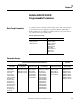
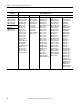
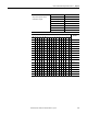
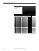

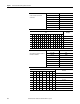
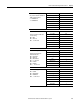
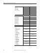
Table Of Contents
- ArmorStart Distributed Motor Controller with EtherNet/IP User Manual
- European Communities (EC) Directive Compliance
- Table of Contents
- Chapter 1
- Product Overview
- Introduction
- Description
- Catalog Number Explanation
- Operation
- Mode of Operation
- Description of Features
- Embedded Switch Technology
- Switched vs. Unswitched Control Power Input/Output (I/O) Connections
- EtherNet/IP™ Ports
- Embedded Web Server
- EtherNet/IP LED Status Indication
- Control Module LED Status and Reset
- Electronic Data Sheet (EDS)
- Fault Diagnostics
- Standard Features
- Factory-Installed Options
- Optional HOA Keypad Configuration (Bulletin 280E/281E only)
- Optional HOA Selector Keypad with Jog Function (Bulletin 284E only)
- Source Brake Contactor and Connector (Bulletin 284E only)
- EMI Filter (Bulletin 284E only)
- Dynamic Brake Connector (Bulletin 284E only)
- IP67 Dynamic Brake Resistor (Bulletin 284E only)
- Output Contactor (Bulletin 284E only)
- Shielded Motor Cable (Bulletin 284E only)
- ArmorStart® EtherNet/ IP Features
- Notes:
- Product Overview
- Chapter 2
- Installation and Wiring
- Receiving
- Unpacking
- Inspecting
- Storing
- General Precautions
- Precautions for Bulletin 280E/281E Applications
- Precautions for Bulletin 284E Applications
- Dimensions
- Mount Orientation
- Operation
- Wiring
- Terminal Designations
- Control Power Wiring
- ArmorStart with EtherNet/IP Internal Wiring
- AC Supply Considerations for Bulletin 284E Units
- Electromagnetic Compatibility (EMC)
- Grounding
- ArmorConnect Power Media
- ArmorConnect Connections
- ArmorConnect Cable Ratings
- Ethernet and I/O Connections
- Power Connections
- Optional Locking Clip
- Installation and Wiring
- Chapter 3
- Chapter 4
- Chapter 5
- Chapter 6
- Chapter 7
- Bulletin 280E/281E/284E Programmable Parameters
- Basic Setup Parameters
- Parameter Groups
- ArmorStart EtherNet/IP Parameters
- Bulletin 280E/281E
- Bulletin 284E
- Basic Status Group
- Produced Assembly Config Group
- Starter Protection Group
- User I/O Configuration Group
- Miscellaneous Configuration Group
- Drive I/O Configuration Group (Bulletin 284E only)
- Drive Display Group (Bulletin 284E only)
- Drive Setup Group (Bulletin 284E only)
- Drive Advanced Setup Group (Bulletin 284E only)
- Clear a Type 1 Fault and Restart the Drive
- Clear an Overvoltage, Undervoltage, or Heatsink OvrTmp Fault without Restarting the Drive
- How StepLogic Works
- StepLogic Settings
- Linear List of Parameters for Bulletin 280E/281E and Bulletin 284E
- Bulletin 280E/281E/284E Programmable Parameters
- Chapter 8
- Chapter 9
- Chapter 10
- Chapter 11
- Chapter 12
- Appendix A
- Applying More Than One ArmorStart Motor Controller in a Single Branch Circuit on Industrial Machinery
- Introduction
- ArmorStart LT Product Family
- Multiple-Motor Branch Circuits and Motor Controllers Listed for Group Installation – General
- Maximum Fuse Ampere Rating According to 7.2.10.4(1) and 7.2.10.4(2)
- Explanatory Example
- Input and Output Conductors of Bulletin 290E and 291E Controllers (a)
- Input and Output Conductors of Bulletin 294E Controllers (b)
- Combined Load Conductors (c)
- Applying More Than One ArmorStart Motor Controller in a Single Branch Circuit on Industrial Machinery
- Appendix B
- CIP Information
- High Level Product Description
- CIP Explicit Connection Behavior
- CIP Object Requirements
- Identity Object
- Assembly Object
- Connection Manager Object
- Discrete Input Point Object
- Discrete Output Point Object
- Parameter Object
- Parameter Group Object
- Discrete Input Group Object
- Discrete Output Group Object
- Control Supervisor Object
- Overload Object
- Device Level Ring (DLR) Object
- Qos Object
- DPI Fault Object
- DPI Alarm Object
- Interface Object
- TCP/IP Interface Object
- Ethernet Link Object
- CIP Information
- Appendix C
- Using DeviceLogix
- DeviceLogix Programming
- DeviceLogix Programming Example
- Import and Export
- Bulletin 284 - VFD Preset Speed Example
- DeviceLogix Ladder Editor Example
- ArmorStart 280 and 281 Status Bits
- Bulletin 280 and 281 ArmorStart Fault Bits
- Bulletin 280 and 281 ArmorStart Outputs
- Bulletin 280 and 281 ArmorStart Produced Network Bits
- Bulletin 284 ArmorStart Status Bits
- Bulletin 284 ArmorStart Fault Bits
- Bulletin 284 ArmorStart Outputs
- Bulletin 284 ArmorStart Produced Network Bits
- Using DeviceLogix
- Appendix D
- Appendix E
- Appendix F
- Back Cover

Rockwell Automation Publication 280E-UM001B-EN-P - July 2012 111
Chapter 7
Bulletin 280E/281E/284E
Programmable Parameters
Basic Setup Parameters
To configure the basic ArmorStart functionality refer to Table18 below. These
are the minimum setup configurations required for Bulletin 280E/281E or
Bulletin 284E. There are additional capabilities and motor protection that are
not enabled or left at their default values.
Parameter Groups
Table 18 - Quick Parameter Setup
Bulletin 280E/281E Bulletin 284E
106 FLA Setting
107 Overload Class
108 OL Reset Level
131 Motor NP Volts
132 Motor NP Hertz
133 Motor OL Current
134 Minimum Freq
135 Maximum Freq
137 Stop Mode
138 Speed Reference
139 Accel Time 1
140 Decel Time 1
Common to Bulletin 280E/281E and Bulletin 284E Units
Bulletin 284E
Units Only
Basic Status
Produced Assembly
Config Group
Starter Protection User I/O Config Miscellaneous Config Drive I/O Config
1 Hdw Inputs
2 DeviceIn Data
3 DeviceOut Data
4 Trip Status
5 Starter Status
6 InternalLinkStat
7 Starter Command
22 Breaker Type
56 Base Enclosure
57 Base Options
58 Wiring Options
59 Starter Enclosure
60 Starter Options
61 Last Pr Fault
62 Warning Status
63 Base Trip
13 Int00DeviceOut Cfg
14 Int01DeviceOut Cfg
15 Int02DeviceOut Cfg
16 Int03DeviceOut Cfg
23 Pr FltResetMode
24 Pr Fault Enable
25 Pr Fault Reset
26 Str Net FltState
27 Str Net FltValue
28 Str Net IdlState
29 Str Net IdlValue
30 Anti-bounce On Delay
31 Anti-bounce OFF Delay
32 In Sink/Source
33 OutA Pr FltState
34 OutA Pr FltValue
35 OutA Net FltState
36 OutA Net FltValue
37 OutA Net IdlState
38 OutA Net IdlValue
39 OutB Pr FltState
40 OutB Pr FltValue
41 OutB Net FltState
42 OutB Net FltValue
43 OutB Net IdlState
44 OutB Net IdlValue
8 Network Override
9 Comm Override
45 Keypad Mode
46 Keypad Disable
47 Set To Defaults
48 Drive Control
49 DrvIn Pr FltState
50 DrvIn Pr FltValue
51 DrvIn Net FltState
52 DrvIn Net FltValue
53 DrvIn Net IdlState
54 DrvIn Net IdlValue
55 High Speed Enable