
User Manual Owner's manual
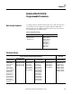
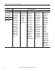
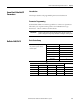
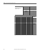
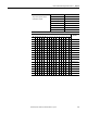
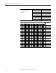
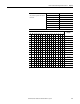
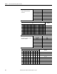
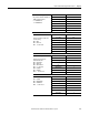
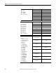
Table Of Contents
- ArmorStart Distributed Motor Controller with EtherNet/IP User Manual
- European Communities (EC) Directive Compliance
- Table of Contents
- Chapter 1
- Product Overview
- Introduction
- Description
- Catalog Number Explanation
- Operation
- Mode of Operation
- Description of Features
- Embedded Switch Technology
- Switched vs. Unswitched Control Power Input/Output (I/O) Connections
- EtherNet/IP™ Ports
- Embedded Web Server
- EtherNet/IP LED Status Indication
- Control Module LED Status and Reset
- Electronic Data Sheet (EDS)
- Fault Diagnostics
- Standard Features
- Factory-Installed Options
- Optional HOA Keypad Configuration (Bulletin 280E/281E only)
- Optional HOA Selector Keypad with Jog Function (Bulletin 284E only)
- Source Brake Contactor and Connector (Bulletin 284E only)
- EMI Filter (Bulletin 284E only)
- Dynamic Brake Connector (Bulletin 284E only)
- IP67 Dynamic Brake Resistor (Bulletin 284E only)
- Output Contactor (Bulletin 284E only)
- Shielded Motor Cable (Bulletin 284E only)
- ArmorStart® EtherNet/ IP Features
- Notes:
- Product Overview
- Chapter 2
- Installation and Wiring
- Receiving
- Unpacking
- Inspecting
- Storing
- General Precautions
- Precautions for Bulletin 280E/281E Applications
- Precautions for Bulletin 284E Applications
- Dimensions
- Mount Orientation
- Operation
- Wiring
- Terminal Designations
- Control Power Wiring
- ArmorStart with EtherNet/IP Internal Wiring
- AC Supply Considerations for Bulletin 284E Units
- Electromagnetic Compatibility (EMC)
- Grounding
- ArmorConnect Power Media
- ArmorConnect Connections
- ArmorConnect Cable Ratings
- Ethernet and I/O Connections
- Power Connections
- Optional Locking Clip
- Installation and Wiring
- Chapter 3
- Chapter 4
- Chapter 5
- Chapter 6
- Chapter 7
- Bulletin 280E/281E/284E Programmable Parameters
- Basic Setup Parameters
- Parameter Groups
- ArmorStart EtherNet/IP Parameters
- Bulletin 280E/281E
- Bulletin 284E
- Basic Status Group
- Produced Assembly Config Group
- Starter Protection Group
- User I/O Configuration Group
- Miscellaneous Configuration Group
- Drive I/O Configuration Group (Bulletin 284E only)
- Drive Display Group (Bulletin 284E only)
- Drive Setup Group (Bulletin 284E only)
- Drive Advanced Setup Group (Bulletin 284E only)
- Clear a Type 1 Fault and Restart the Drive
- Clear an Overvoltage, Undervoltage, or Heatsink OvrTmp Fault without Restarting the Drive
- How StepLogic Works
- StepLogic Settings
- Linear List of Parameters for Bulletin 280E/281E and Bulletin 284E
- Bulletin 280E/281E/284E Programmable Parameters
- Chapter 8
- Chapter 9
- Chapter 10
- Chapter 11
- Chapter 12
- Appendix A
- Applying More Than One ArmorStart Motor Controller in a Single Branch Circuit on Industrial Machinery
- Introduction
- ArmorStart LT Product Family
- Multiple-Motor Branch Circuits and Motor Controllers Listed for Group Installation – General
- Maximum Fuse Ampere Rating According to 7.2.10.4(1) and 7.2.10.4(2)
- Explanatory Example
- Input and Output Conductors of Bulletin 290E and 291E Controllers (a)
- Input and Output Conductors of Bulletin 294E Controllers (b)
- Combined Load Conductors (c)
- Applying More Than One ArmorStart Motor Controller in a Single Branch Circuit on Industrial Machinery
- Appendix B
- CIP Information
- High Level Product Description
- CIP Explicit Connection Behavior
- CIP Object Requirements
- Identity Object
- Assembly Object
- Connection Manager Object
- Discrete Input Point Object
- Discrete Output Point Object
- Parameter Object
- Parameter Group Object
- Discrete Input Group Object
- Discrete Output Group Object
- Control Supervisor Object
- Overload Object
- Device Level Ring (DLR) Object
- Qos Object
- DPI Fault Object
- DPI Alarm Object
- Interface Object
- TCP/IP Interface Object
- Ethernet Link Object
- CIP Information
- Appendix C
- Using DeviceLogix
- DeviceLogix Programming
- DeviceLogix Programming Example
- Import and Export
- Bulletin 284 - VFD Preset Speed Example
- DeviceLogix Ladder Editor Example
- ArmorStart 280 and 281 Status Bits
- Bulletin 280 and 281 ArmorStart Fault Bits
- Bulletin 280 and 281 ArmorStart Outputs
- Bulletin 280 and 281 ArmorStart Produced Network Bits
- Bulletin 284 ArmorStart Status Bits
- Bulletin 284 ArmorStart Fault Bits
- Bulletin 284 ArmorStart Outputs
- Bulletin 284 ArmorStart Produced Network Bits
- Using DeviceLogix
- Appendix D
- Appendix E
- Appendix F
- Back Cover

112 Rockwell Automation Publication 280E-UM001B-EN-P - July 2012
Chapter 7 Bulletin 280E/281E/284E Programmable Parameters
Bulletin280E/281E
Units Only Bulletin 284E Units Only
Starter Display Drive Display Drive Setup Drive Advanced Setup
101 Phase A Current
102 Phase B Current
103 Phase C Current
104 Average Current
105 Therm Utilized
101 Output Freq
102 Commanded Freq
103 Output Current
104 Output Voltage
105 DC Bus Voltage
106 Drive Status
107 Fault 1 Code
108 Fault 2 Code
109 Fault 3 Code
110 Process Display
112 Control Source
113 Contrl In Status
114 Dig In Status
115 Comm Status
116 Control SW Ver
117 Drive Type
118 Elapsed Run Time
119 Testpoint Data
122 Output Power
123 Output Power Fctr
124 Drive Temp
125 Counter Status
126 Timer Status
128 StpLogic Status
129 Torque Current
131 Motor NP Volts
132 Motor NP Hertz
133 Motor OL Current
134 Minimum Freq
135 Maximum Freq
136 Start Source
137 Stop Mode
138 Speed Reference
139 Accel Time 1
140 Decel Time 1
141 Reset To Defaults
143 Motor OL Ret
151 Digital In 1 Sel
152 Digital In 2 Sel
153 Digital In 3 Sel
154 Digital In 4 Sel
155 Relay Out Sel
156 Relay Out Level
167 Accel Time 2
168 Decel Time 2
169 Internal Freq
170 Preset Freq 0
171 Preset Freq 1
172 Preset Freq 2
173 Preset Freq 3
174 Preset Freq 4
175 Preset Freq 5
176 Preset Freq 6
177 Preset Freq 7
178 Jog Frequency
179 Jog Accel/Decel
180 DC Brake Time
181 DC Brake Level
182 DB Resistor Sel
183 S Curve %
184 Boost Select
185 Start Boost
186 Brake Voltage
187 Brake Frequency
188 Maximum Voltage
189 Current Limit 1
190 Motor OL Select
191 PWM Frequency
192 Auto Rstrt Tries
193 Auto Rstrt Delay
194 Start At PowerUp
195 Reverse Disable
196 Flying Start En
197 Compensation
198 SW Current Trip
199 Process Factor
200 Fault Clear
201 Program Lock
202 Testpoint Sel
205 Comm Loss Action
206 Comm Loss Time
214 Slip Hertz @ FLA
215 Process Time Lo
216 Process Time Hi
217 Bus Reg Mode
218 Current Limit 2
219 Skip Frequency
220 Skip Freq Band
221 Stall Fault Time
224 Var PWM Disable
225 Torque Perf Mode
226 Motor NP FLA
227 Autotune
228 IR Voltage Drop
229 Flux Current Ref
230 PID Trim Hi
231 PID Trim Lo
232 PID Ref Sel
233 PID Feedback Sel
234 PID Prop Gain
235 PID Integ Time
236 PID Diff Rate
237 PID Setpoint
238 PID Deadband
239 PID Preload
240 StpLogic 0
241 StpLogic 1
242 StpLogic 2
243 StpLogic 3
244 StpLogic 4
245 StpLogic 5
246 StpLogic 6
247 StpLogic 7
250 StpLogic Time 0
251 StpLogic Time 1
252 StpLogic Time 2
253 StpLogic Time 3
254 StpLogic Time 4
255 StpLogic Time 5
256 StpLogic Time 6
257 StpLogic Time 7
260 EM Brk OFF Delay
261 EM Brk On Delay
262 MOP Reset Sel
263 DB Threshold
264 Comm Write Mode
267 PID Invert Error
Starter Setup
106 FLA Setting
107 Overload Class
108 OL Reset Level