
User Manual Owner's manual
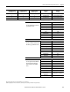
Table Of Contents
- ArmorStart Distributed Motor Controller with EtherNet/IP User Manual
- European Communities (EC) Directive Compliance
- Table of Contents
- Chapter 1
- Product Overview
- Introduction
- Description
- Catalog Number Explanation
- Operation
- Mode of Operation
- Description of Features
- Embedded Switch Technology
- Switched vs. Unswitched Control Power Input/Output (I/O) Connections
- EtherNet/IP™ Ports
- Embedded Web Server
- EtherNet/IP LED Status Indication
- Control Module LED Status and Reset
- Electronic Data Sheet (EDS)
- Fault Diagnostics
- Standard Features
- Factory-Installed Options
- Optional HOA Keypad Configuration (Bulletin 280E/281E only)
- Optional HOA Selector Keypad with Jog Function (Bulletin 284E only)
- Source Brake Contactor and Connector (Bulletin 284E only)
- EMI Filter (Bulletin 284E only)
- Dynamic Brake Connector (Bulletin 284E only)
- IP67 Dynamic Brake Resistor (Bulletin 284E only)
- Output Contactor (Bulletin 284E only)
- Shielded Motor Cable (Bulletin 284E only)
- ArmorStart® EtherNet/ IP Features
- Notes:
- Product Overview
- Chapter 2
- Installation and Wiring
- Receiving
- Unpacking
- Inspecting
- Storing
- General Precautions
- Precautions for Bulletin 280E/281E Applications
- Precautions for Bulletin 284E Applications
- Dimensions
- Mount Orientation
- Operation
- Wiring
- Terminal Designations
- Control Power Wiring
- ArmorStart with EtherNet/IP Internal Wiring
- AC Supply Considerations for Bulletin 284E Units
- Electromagnetic Compatibility (EMC)
- Grounding
- ArmorConnect Power Media
- ArmorConnect Connections
- ArmorConnect Cable Ratings
- Ethernet and I/O Connections
- Power Connections
- Optional Locking Clip
- Installation and Wiring
- Chapter 3
- Chapter 4
- Chapter 5
- Chapter 6
- Chapter 7
- Bulletin 280E/281E/284E Programmable Parameters
- Basic Setup Parameters
- Parameter Groups
- ArmorStart EtherNet/IP Parameters
- Bulletin 280E/281E
- Bulletin 284E
- Basic Status Group
- Produced Assembly Config Group
- Starter Protection Group
- User I/O Configuration Group
- Miscellaneous Configuration Group
- Drive I/O Configuration Group (Bulletin 284E only)
- Drive Display Group (Bulletin 284E only)
- Drive Setup Group (Bulletin 284E only)
- Drive Advanced Setup Group (Bulletin 284E only)
- Clear a Type 1 Fault and Restart the Drive
- Clear an Overvoltage, Undervoltage, or Heatsink OvrTmp Fault without Restarting the Drive
- How StepLogic Works
- StepLogic Settings
- Linear List of Parameters for Bulletin 280E/281E and Bulletin 284E
- Bulletin 280E/281E/284E Programmable Parameters
- Chapter 8
- Chapter 9
- Chapter 10
- Chapter 11
- Chapter 12
- Appendix A
- Applying More Than One ArmorStart Motor Controller in a Single Branch Circuit on Industrial Machinery
- Introduction
- ArmorStart LT Product Family
- Multiple-Motor Branch Circuits and Motor Controllers Listed for Group Installation – General
- Maximum Fuse Ampere Rating According to 7.2.10.4(1) and 7.2.10.4(2)
- Explanatory Example
- Input and Output Conductors of Bulletin 290E and 291E Controllers (a)
- Input and Output Conductors of Bulletin 294E Controllers (b)
- Combined Load Conductors (c)
- Applying More Than One ArmorStart Motor Controller in a Single Branch Circuit on Industrial Machinery
- Appendix B
- CIP Information
- High Level Product Description
- CIP Explicit Connection Behavior
- CIP Object Requirements
- Identity Object
- Assembly Object
- Connection Manager Object
- Discrete Input Point Object
- Discrete Output Point Object
- Parameter Object
- Parameter Group Object
- Discrete Input Group Object
- Discrete Output Group Object
- Control Supervisor Object
- Overload Object
- Device Level Ring (DLR) Object
- Qos Object
- DPI Fault Object
- DPI Alarm Object
- Interface Object
- TCP/IP Interface Object
- Ethernet Link Object
- CIP Information
- Appendix C
- Using DeviceLogix
- DeviceLogix Programming
- DeviceLogix Programming Example
- Import and Export
- Bulletin 284 - VFD Preset Speed Example
- DeviceLogix Ladder Editor Example
- ArmorStart 280 and 281 Status Bits
- Bulletin 280 and 281 ArmorStart Fault Bits
- Bulletin 280 and 281 ArmorStart Outputs
- Bulletin 280 and 281 ArmorStart Produced Network Bits
- Bulletin 284 ArmorStart Status Bits
- Bulletin 284 ArmorStart Fault Bits
- Bulletin 284 ArmorStart Outputs
- Bulletin 284 ArmorStart Produced Network Bits
- Using DeviceLogix
- Appendix D
- Appendix E
- Appendix F
- Back Cover

Rockwell Automation Publication 280E-UM001B-EN-P – July 2012 165
Bulletin 280E/281E/284E Programmable Parameters Chapter 7
Table 20 - Digital Input Options
Option Name Description
0 Not Used
Terminal has no function but can be read over network communication via Parameter 114 (Dig In Status).
1 Acc2 & Dec2
• When active, Parameter 167 (Accel Time 2) and Parameter 168 (Decel Time 2) are used for all ramp rates except Jog.
• Can only be tied to one input.
2 Jog
• When input is present, drive accelerates according to the value set in Parameter 179 (Jog Accel/Decel) and ramps to the value set in
Parameter 178 (Jog Frequency).
• When the input is removed, drive ramps to a stop according to the value set in Parameter 179 (Jog Accel/Decel).
• A valid Start command will override this input.
3 Aux Fault When enable, an F2, Auxiliary Input fault will occur when the input is removed.
4
Preset Freq
(Parameters 151 and
152 Default)
Refer to Parameters 170…173 and 174…177.
5
Local (Parameter 153
Default)
Option not valid for Bulletin 284E ArmorStart.
6 Comm Port This option is the default setting.
7 Clear Fault When active, clears active fault.
8 RampStop,CF Causes drive to immediately ramp to stop regardless of how Parameter 137 (Stop Mode) is set.
9 CoastStop,CF Causes drive to immediately ramp to stop regardless of how Parameter 137 (Stop Mode) is set.
10 DCInjStop,CF Causes drive to immediately begin a DC Injection stop regardless of how Parameter 137 (Stop Mode) is set.
11
Jog Forward
(Parameter 154
Default)
Drive accelerates to Parameter 178 (Jog Frequency) according to Parameter 179 (Jog Accel/Decel) and ramps to stop when input becomes
inactive. A valid start will override this command.
12 Jog Reverse
Drive accelerates to Parameter 178 (Jog Frequency) according to Parameter 179 (Jog Accel/Decel) and ramps to stop when input becomes
inactive. A valid start will override this command.
13 10V In Ctrl Option not valid for Bulletin 284E ArmorStart.
14 20MA In Ctrl Option not valid for Bulletin 284E ArmorStart.
15 PID Disable Disabled PID function. Drive uses the next valid non-PID speed reference.
16 MOP Up Increases the value of Parameter 169 (Internal Freq) at a rate 2 Hz per second. Default of Parameter 169 is 60 Hz.
17 MOP Down Decreases the value of Parameter 169 (Internal Freq) at a rate 2 Hz per second. Default of Parameter 169 is 60 Hz.
18 Timer Start Clears and starts the timer function. May be used to control the relay
19 Counter In Starts the counter function. May be used to control the relay.
20 Reset Timer Clears the active timer.
21 Reset Countr Clears the active counter.
22 Rset Tim & Cnt Clear active timer and counter.
23 Logic In1
Logic Function input number 1. May be used to control the relay (see Parameter 155, Options 11…14). May be used in conjunction with
StepLogic Parameters 240…247 (StpLogic X).
24 Logic In2
Logic Function input number 2. May be used to control the relay (see Parameter 155, Options 11…14). May be used in conjunction with
StepLogic Parameters 240…247 (StpLogic X).
25 Current Lmt2 When active, Parameter 218 (Current Limit 2) determines the drive current limit level.
26 Anlg Invert Option not valid for Bulletin 284E ArmorStart.
27 ➊ Em Brk Rise If EM Brake function enabled, this input releases the brake.
➊ Provides programmable control of Em Brk via digital input (1...4)